
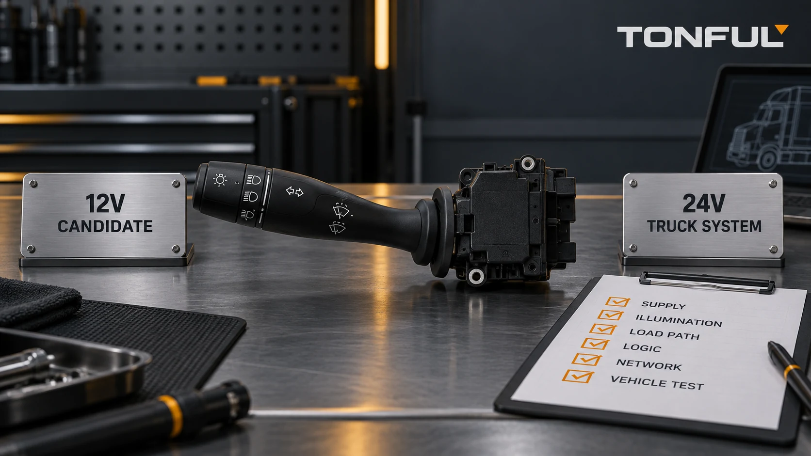
Do not install a 12V combination switch in a 24V truck merely because the housing, connector or OE reference looks similar. A truck’s nominal voltage does not prove that every switch terminal operates at 24V, but a “12V” label also does not prove that the assembly can safely tolerate the truck’s electrical loads, abnormal supply conditions or control architecture.
The answer can be yes only when controlled product and vehicle evidence verifies every affected circuit. In many applications the safe answer is no: 12V illumination, PCB components, suppression devices, resistor networks or communication interfaces can be damaged or misread in a 24V environment. Even a contact-only switch needs verified DC load, interruption, voltage-drop, temperature and endurance capability.
On this page: Define Each Voltage Domain | Identify the Load Path | Evaluate Mismatch Risks | Validate Before Release
Define Each Voltage Domain
Nominal Vehicle Voltage Is Not Every Terminal Voltage
A nominal 24V vehicle system may contain several electrical domains. Record each one from the controlled vehicle diagram and product specification:
| Circuit domain | What to verify | Why the 12V/24V label is insufficient |
|---|---|---|
| Vehicle supply | Nominal and specified operating range | Charging and abnormal conditions differ from the nominal marking |
| Switch electronics | Supply pins, protection and regulator range | PCB devices can fail even when mechanical contacts would survive |
| Illumination/indicators | Supply, polarity, current control and PWM dimming | A 12V LED/resistor network can be overstressed at a higher supply |
| Direct load | Running, starting/inrush and stall conditions | Motor and lamp current paths need contact and terminal evidence |
| Relay control | Coil voltage, suppression and switching polarity | The stalk may switch only a coil, not the final load |
| Logic/reference | Pull-up voltage, resistance windows and thresholds | Module inputs may use a low-voltage reference inside a 24V truck |
| LIN/CAN interface | Transceiver supply, wake and message/software version | Network compatibility is not established by vehicle voltage |
The 12V versus 24V combination-switch guide explains these design domains in detail. For this retrofit decision, build a terminal-by-terminal map rather than applying one voltage label to the whole assembly.
Classify the Candidate Switch
Separate a passive contact assembly from a switch containing LEDs, resistors, a PCB, a voltage regulator, suppression, diagnostics or network communication. A passive switch is not automatically voltage-independent: direct-current interruption, contact gap, arcing, material, terminal capacity and insulation remain relevant. An electronic switch is more likely to have defined supply, overvoltage, reverse-polarity, brownout and recovery requirements.
Inspect the actual revision. Two housings may share a connector while one contains only contacts and another contains a coded or network board. The analog, resistive, LIN and CAN guide helps identify the architecture without assuming a universal pinout.

A 24V truck can contain multiple voltage and signal domains; verify every switch circuit from controlled documents.
Identify the Load Path
Direct-Load Contacts
Some combination switches carry lamp or motor current directly. For every position, identify the source, downstream load, protective device, conductor path and return. Record steady-state current plus applicable inrush, motor start or stall condition. Verify contact material, DC make/break capability, terminal and connector capacity, loaded voltage drop, temperature rise and endurance using the customer/OEM plan.
Do not argue that a 24V system is easier because equal power may draw less steady current. Higher DC voltage can change arc behavior, and the real load may not have equal power. A motor, lamp, relay or electronic module can present transient conditions that are not represented by a simple wattage calculation.
The combination-switch contact-resistance test guide explains why resistance, loaded voltage drop, test points and load conditions must be documented. Its example values must not replace the project drawing or approved acceptance plan.
Relay or Module Requests
If the stalk drives a relay coil or module input, verify coil voltage, suppression orientation, switched side, input thresholds and fault detection. A switch may appear to carry little current yet include an indicator, resistor ladder or semiconductor that is connected to a different supply domain.
For a resistance-coded input, measure every maintained and momentary state under the specified reference circuit. Compare nominal values, tolerances, transitions and open-circuit behavior with the receiving module’s thresholds. For LIN/CAN systems, confirm transceiver hardware, protocol, baud/configuration, message set, wake/sleep behavior, software revision and diagnostic response. A 12V network switch is not approved for a 24V truck just because both vehicles use LIN.
Connector and Pinout
Record the viewing direction and every cavity, including blanks. Compare supplies, grounds, illumination, loads, relay requests, reference/return and communication lines. The connector, terminal and harness checklist provides the necessary fields.
Never apply 24V to unknown pins as a discovery method. Use controlled diagrams, current-limited fixtures and qualified personnel. A same-shell connector can place truck supply on a 12V illumination or module input and cause immediate or latent damage.
Evaluate Mismatch Risks
What Can Happen When Voltages Are Mixed?
| Mismatch | Possible result | Required evidence |
|---|---|---|
| 12V illumination connected to 24V | LED, resistor, driver or symbol lighting overstress | Illumination rating, polarity, PWM and thermal test |
| 24V illumination used on 12V | Dim, unstable or absent light | Starting voltage, brightness range and dimming behavior |
| 12V electronic switch on 24V supply | Regulator, capacitor, protection or transceiver damage | Operating range and approved electrical-load plan |
| 24V module on 12V supply | Brownout, repeated reset, missing communication or DTCs | Undervoltage behavior and recovery evidence |
| Passive switch substituted by connector fit | Wrong load path, contact stress or reversed function | Pinout, contact map and load-specific validation |
| Coded switch crossed between systems | Wrong decoded state or intermittent threshold crossing | Reference circuit, resistance/voltage windows and tolerance |
| Network switch crossed between systems | No communication, wrong command or configuration fault | Hardware, protocol, messages, software and diagnostics |
Overvoltage damage is not always immediate. Illumination can still work while running hotter than intended; protection can degrade; or contact wear can accelerate under a different interruption condition. The absence of a failure during a short bench check is not endurance evidence.
When Could a 12V-Labeled Switch Be Considered?
A candidate may proceed to validation when controlled supplier documentation shows that the exact revision supports the required 24V electrical domain, or when the “12V” catalog description applies only to a vehicle application and every affected circuit is independently rated and verified for the truck. A passive contact switch might also be technically usable when its DC ratings, load paths, terminals, insulation, mechanical interfaces and full function matrix satisfy the 24V project.
This is not permission to generalize across a switch family. Approval must name the part revision, vehicle application, loads, connector population and evidence. If any electronic or illumination circuit lacks a defined range, treat the substitution as unverified.
Validate Before Release
Build the Electrical Verification Matrix
| Verification item | Required record |
|---|---|
| Vehicle and component definition | Truck model/market, production boundary, OE number and switch revision |
| Nominal and operating supply | Controlled vehicle and component specification |
| Cranking/brownout behavior | Required function state, reset and recovery under the approved plan |
| Overvoltage/transient response | Applicable severity, wiring mode and acceptance source |
| Reverse polarity | Protected circuits, duration and failure criteria where specified |
| Direct load | Running, inrush/start and stall conditions plus protection |
| Contact performance | Load, test points, voltage drop, temperature and aged result |
| Illumination | Voltage, polarity, PWM/dimming, brightness and temperature |
| Electronic sleep current | Vehicle state, settling time, measurement and limit source |
| Network/coded interface | Reference circuit or protocol, messages, software and DTC behavior |
| Recovery | Function, stored faults and reinitialization after supply disturbance |
ISO 16750-2:2023 addresses electrical loads for electrical and electronic equipment in road vehicles. It does not supply one universal test severity or prove that a particular 12V switch is compatible with a 24V truck. Select the applicable conditions and acceptance criteria from the customer/OEM specification and approved qualification plan.
Follow a Staged Test Sequence
- Freeze the candidate revision and vehicle scope.
- Review diagrams, product specifications and cavity maps before energizing.
- Inspect mounting, connector keying, terminal population and harness condition.
- Verify passive state continuity, coded values or network identity on a protected bench.
- Apply only the approved supply and load conditions with suitable protection and instrumentation.
- Measure raw switch output separately from downstream vehicle response.
- Check illumination, every stalk function, return/cancel and optional control.
- Perform required electrical-load, thermal, mechanical and endurance validation.
- Install a production-intent sample and inspect DTCs, initialization and complete vehicle operation.
- Record approval status, source documents, reviewer, date and change-control boundary.

A protected staged test separates switch input, load path and vehicle response without guessing unknown terminals.
Release Decision
Approve only when all required physical, electrical, functional and vehicle evidence agrees. A conditional approval must identify the unresolved item, permitted quantity or application, owner, expiry and closure evidence. Reject the substitution when a mandatory voltage range, load capability, pinout, architecture, function or installed-vehicle criterion fails.
The same-connector interchangeability guide explains why physical mating is only one gate. For sourcing, include the voltage-domain matrix and validation evidence in the combination-switch RFQ checklist rather than requesting a generic “12V or 24V equivalent.”
Work With TONFUL
TONFUL’s automotive combination switch range includes current 12V and 24V application references. Send the truck/VIN scope, OE label, connector end views, cavity map, circuit diagram, electrical loads, illumination requirements and function matrix. TONFUL can review the exact candidate and sample-validation scope; voltage marking or connector fit alone is not treated as approval for a 24V truck.