
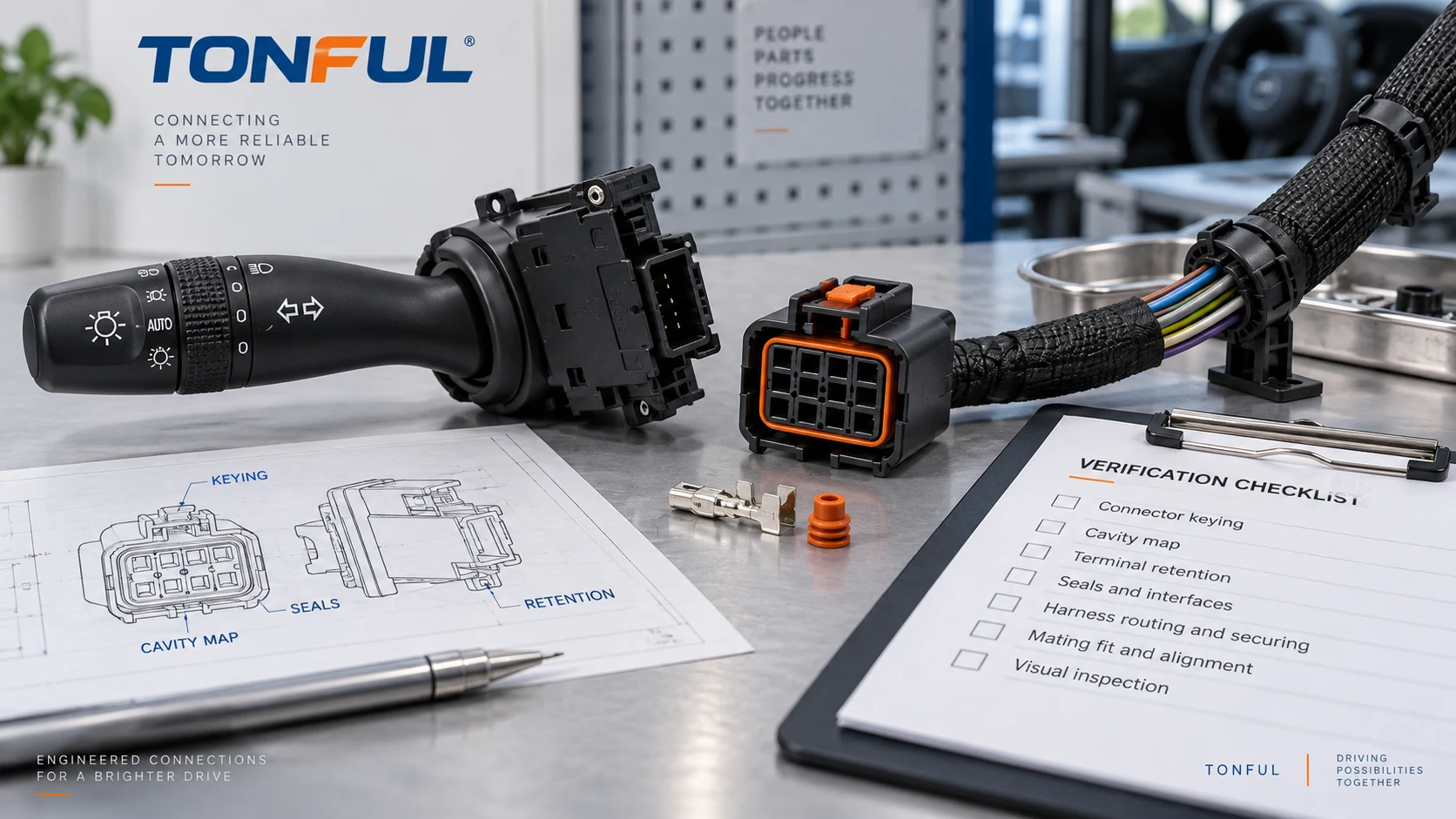
Two stalk switches can accept the same-looking plug and still be incompatible. The shell may have different keying, the same cavity may serve a different circuit, one terminal family may not mate correctly, or a heavier load may exceed the wire and contact system. Even a correct electrical map can fail in service if the connector is not fully seated, the secondary lock is open or the harness pulls sideways on the switch.
A replacement release should therefore treat the interface as a controlled system: switch header, mating housing, terminals, seals, cavity map, wire, splices, strain relief and vehicle circuit. This checklist converts those elements into evidence that buyers, technicians and quality teams can record.
On this page: Identify the Interface | Verify Terminals and Wires | Test the Complete Circuit | Release Checklist
Identify the Interface
Control Viewing Direction and Cavity Numbers
Start with the product drawing or vehicle wiring information. Record whether the connector view is the switch header, mating face, wire-entry face or harness side. Mark the latch, key and orientation reference. A mirrored photograph can turn a correct pin table into a wrong connection.
Use one cavity identifier throughout photographs, continuity records and test fixtures. Do not renumber populated positions sequentially when the housing includes blanks. The combination switch pinout guide provides a detailed orientation method.
| Interface field | Removed switch/harness | Candidate | Evidence source | Result |
|---|---|---|---|---|
| Header/housing ID | Enter | Enter | Drawing/marking | Pass/Fail |
| Viewing direction | Enter | Enter | Controlled end-view photo | Pass/Fail |
| Position count | Enter | Enter | Drawing | Pass/Fail |
| Key/polarization | Enter | Enter | Dimensions/fit | Pass/Fail |
| Latch and CPA | Enter | Enter | Drawing/inspection | Pass/Fail |
| Populated cavities | Enter | Enter | Cavity map | Pass/Fail |
| Terminal family/plating | Enter | Enter | Product spec | Pass/Fail |
| Seals/plugs | Enter | Enter | Application spec | Pass/Fail |
| Harness exit/restraint | Enter | Enter | Vehicle installation | Pass/Fail |
Compare More Than Shell Shape
Measure housing envelope, key geometry, latch engagement, connector depth and clearance to column trim. Check terminal position assurance (TPA), connector position assurance (CPA), backshell and strain relief where present. Similar color is not evidence of the same connector family or revision.
Mate production parts without forcing, shaving keys or removing locks. Record insertion and extraction behavior using the applicable product specification when required. A connector that can be pushed together on a bench may still have incomplete latch travel or terminal wipe.
TE Connectivity’s automotive connector pages illustrate why a controlled connector family can have separate product drawings, application specifications, qualification reports, retainers and position-assurance parts. For example, its DEUTSCH DT housing page lists these document types for that specific family. It is an evidence example, not a specification for a TONFUL stalk connector.
Verify Terminals and Wires
Match the Complete Terminal System
Identify terminal part number, gender, contact size, base material, plating, seal compatibility and supported conductor/insulation range. Do not judge a terminal only by tab width. Contact-beam geometry, plating and retention lance must match the housing and header.
Inspect for backed-out terminals, bent beams, damaged lances, plating wear, contamination, corrosion, heat discoloration and spread contacts. Confirm primary retention and secondary lock engagement. If a push-out or retention test is specified, use the approved direction, fixture, rate and limit. The terminal push-out force guide explains how to preserve test conditions and failure mode.
For repaired crimps, verify wire size, conductor material/construction, strip length, conductor crimp, insulation support, seal position and approved tooling. A terminal designed for one wire range should not be made to fit another by doubling conductors or overcrimping. Record tool, applicator/cavity, setup and pull/cross-section evidence as required by the application specification.
Map Wire and Seal Requirements
Record each cavity’s wire color, function, conductor cross-section/AWG, insulation diameter, seal and branch destination. Wire color is an aid, not primary proof; variants and repairs can differ. For unused sealed cavities, verify approved cavity plugs and insertion depth.
| Cavity | Circuit/function | Terminal ID | Wire size/construction | Seal/plug | Load or signal type | Verification |
|---|---|---|---|---|---|---|
| Enter controlled ID | Enter | Enter | Enter | Enter | Direct/relay/coded/network | Drawing/test |
Separate high-current paths, relay coils, grounds, illumination, reference supplies, coded inputs and communication lines. A 24 V vehicle can still have lower-voltage references or transceiver supplies. The 12 V versus 24 V combination switch guide explains this domain boundary.

Fix the viewing direction, latch reference and cavity numbering before comparing terminal or circuit assignments.
Test the Complete Circuit
Verify Pinout and State Matrix
Do not apply power until supplies, grounds and signal types are identified. For a passive switch, record continuity or loaded voltage drop for every maintained, momentary and rotary position. For resistance-coded inputs, capture reference supply, return, raw resistance/voltage windows, tolerance and receiving-module state. For LIN/CAN designs, record power, wake, network identity, software and decoded commands.
The analog, resistive, LIN and CAN stalk guide helps select the correct method. Never use an ohmmeter across powered electronics or bridge unknown cavities.
Verify load path. A switch may carry lamp/motor current, energize a relay coil or send a low-current module request. For direct paths, confirm approved load, inrush/stall where relevant, voltage drop and thermal behavior. For relay/module paths, test request and downstream output separately. Connector and wire capacity must match the actual path, not the vehicle’s nominal voltage alone.
Check Retention, Fretting and Heat Evidence
Terminal resistance can increase through weak contact force, incomplete mating, corrosion, fretting or crimp damage. Under the approved load, measure voltage drop across controlled points and inspect temperature distribution where required. Do not declare a universal millivolt limit; use the connector specification, vehicle drawing or validated comparison method.
If heat damage exists, preserve evidence before disturbing the interface. Distinguish the initiating high-resistance point from secondary melting. Check terminal retention, mating marks, contact beam, crimp, wire, load current and downstream shorts. Replacing only the switch can leave the damaged harness half in service.
Validate Harness Routing
Install the switch with production column trim, steering adjustment and harness clips. Move the column through its allowed positions and operate every stalk function. Confirm the harness does not rub, pinch, twist, pull the connector, obstruct self-cancel parts or contact moving steering components.
Measure slack and bend condition against the vehicle/harness drawing. Check branch protection, clip engagement and service loop. Harness restraint should prevent connector loading without creating a rigid stress concentration near the wire exit.

Validate the mated connector and harness in the production column envelope, including steering adjustment and control operation.
Release Checklist
Copyable Approval Record
| Approval item | Evidence ID | Sample/vehicle | Result | Owner/date |
|---|---|---|---|---|
| OE and product revision | Enter | Enter | Pass/Fail | Enter |
| Housing/key/latch dimensions | Enter | Enter | Pass/Fail | Enter |
| End-view and cavity map | Enter | Enter | Pass/Fail | Enter |
| Terminal family/plating | Enter | Enter | Pass/Fail | Enter |
| Wire and seal compatibility | Enter | Enter | Pass/Fail | Enter |
| Retention/secondary lock | Enter | Enter | Pass/Fail | Enter |
| State/pinout matrix | Enter | Enter | Pass/Fail | Enter |
| Load/coded/network behavior | Enter | Enter | Pass/Fail | Enter |
| Voltage drop/thermal evidence | Enter | Enter | Pass/Fail | Enter |
| Harness routing/strain relief | Enter | Enter | Pass/Fail | Enter |
| Installed vehicle functions | Enter | Enter | Pass/Fail | Enter |
| Final disposition | Enter | Enter | Approved/Conditional/Rejected | Enter |
Approval requires all mandatory fields. “Connector fits” cannot override a wrong circuit map, terminal system or harness path. Conditional approval must define product and vehicle scope, deviation, risk owner, permitted quantity/period and closure evidence.
Incoming inspection should compare labels, shell/keying, terminal population, locks, seals and a controlled electrical identity. Store variants so visually similar connectors cannot be mixed. Changes to housing supplier, terminal, plating, seal, wire, crimp tooling or cavity population require impact review.
Final Decision Questions
- Are connector views and cavity numbers controlled?
- Do the header, housing, keys, latch and assurance devices match?
- Are terminal family, plating, wire and seal combinations approved?
- Are every supply, ground, load and signal cavity mapped?
- Does the state matrix match the removed part and vehicle architecture?
- Are direct loads separated from relay, coded and network requests?
- Do retention, voltage-drop and thermal results meet named requirements?
- Is the harness restrained throughout steering-column movement?
- Has the installed vehicle passed every function and diagnostic check?
- Are sample, evidence, approver and change scope traceable?
Work With TONFUL
Terminal compatibility must also cover current derating and the assembled environment. A terminal family may have different capability with another wire size, insulation diameter, cavity population, ambient temperature or adjacent loaded circuit. Use the connector or terminal supplier’s controlled data and the vehicle load plan rather than transferring a catalog maximum into the application.
For repaired harnesses, record the terminal, seal, wire, crimp tooling and splice location. Verify conductor support and strain relief, then repeat the relevant retention and loaded circuit checks. A good-looking crimp does not prove that the repair preserves sealing, terminal alignment or long-term resistance.
TONFUL’s automotive combination switch range provides current application references. Send the full OE label, vehicle/VIN scope, controlled connector end views, cavity map, terminal/wire specification, harness photos and functional architecture. TONFUL can compare the candidate interface and approved sample with the project evidence; a matching connector shell alone is not treated as interchangeability.