
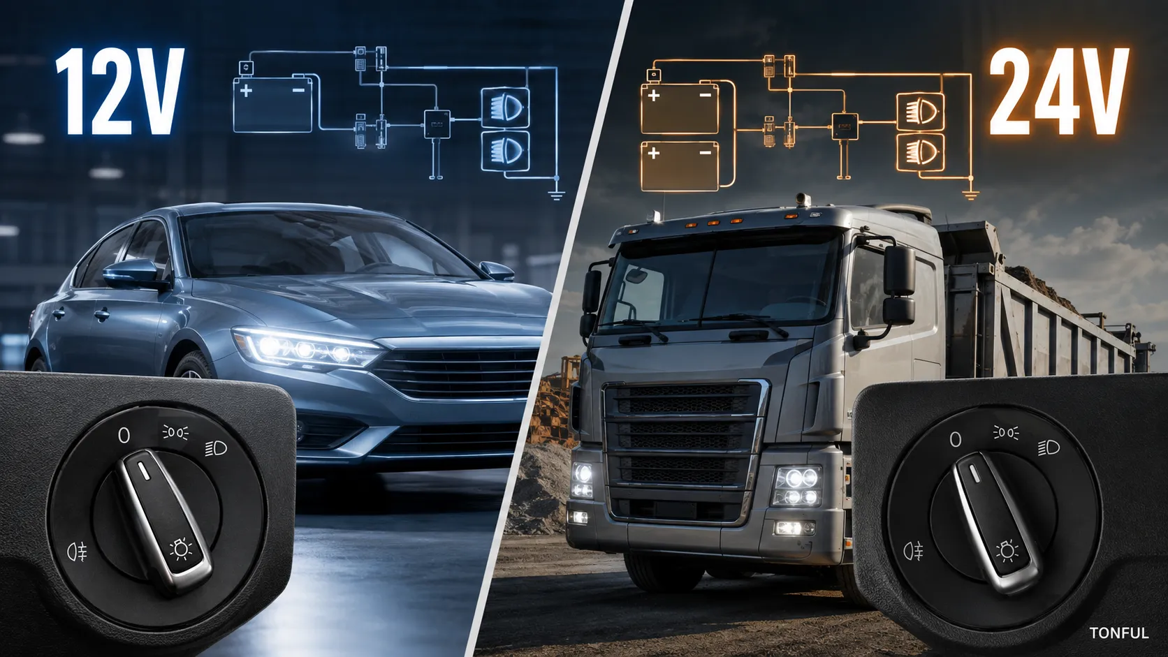
A vehicle’s nominal system voltage does not by itself determine whether a headlight switch can be transferred between 12V and 24V applications. The switch may carry lamp current, energize a voltage-specific relay coil, provide a ground request, feed a resistor network, illuminate internal LEDs, or communicate with a control module. Each path has different voltage, current, transient, connector, and validation requirements.
TONFUL’s current headlight-switch range presents vehicle applications and OE reference numbers. Confirm the exact vehicle, OE chain, connector, pinout, functions, approved sample, and project-specific validation plan before ordering. Product appearance and a shortened cross-reference are not sufficient approval evidence.
At-a-Glance Decision Table

Conceptual illustration only – not a vehicle-specific wiring diagram, fitment record, laboratory result, or acceptance standard.
| Decision area | What it means | What to verify |
|---|---|---|
| Quick Answer: Do Not Substitute by Voltage Label Alone | Passenger cars commonly use nominal 12V systems, while many heavy trucks use nominal 24V systems, but the switch’s actual electrical role is decisive. | Require the product drawing to state rated operating conditions for every circuit. |
| Identify What the Switch Actually Controls | Trace each function from supply through switch or module to relay, lamp, and ground. | Build a function-and-architecture matrix for parking, low beam, high beam request, fog lamps, AUTO, panel dimming, and illumination. |
| Compare Contact Load and Relay-Coil Voltage | At the same power, a higher system voltage can reduce load current, but that does not make contacts automatically interchangeable. | For relay systems, verify coil nominal voltage, suppression type, pickup and dropout behavior, and controller compatibility. |
| Check Illumination, Electronics, and BCM Inputs | Switch backlighting, telltales, resistor ladders, sensors, and internal electronics may have narrower voltage limits than mechanical contacts. | Confirm pin-level supply, ground, reference, signal type, polarity, current, and protection. |
| Heavy-Truck Fitment Adds More Than 24V | Heavy trucks can differ in dashboard geometry, connector systems, sealing, vibration exposure, duty cycle, market lighting functions, trailer interfaces, and service expectations. | Record truck make, model, cab, production range, market, OE reference, connector views, mounting depth, terminal population, functions, and environmental requirements. |
| Validation and RFQ Checklist | A defensible RFQ identifies nominal and operating voltage range, electrical architecture, load or signal for every circuit, protection, connector, pinout, illumination, functions, environment, test method, acceptance source, sample quantity, and change-control needs. | Ask for controlled drawings and test evidence. |
Use the table to identify missing evidence, not to create universal pinouts or ratings. The controlling source is the applicable vehicle information, product drawing, customer specification, or approved validation plan.
Quick Answer: Do Not Substitute by Voltage Label Alone
Passenger cars commonly use nominal 12V systems, while many heavy trucks use nominal 24V systems, but the switch’s actual electrical role is decisive. A dry contact may face different load stress than a relay command or BCM input, and internal illumination can remain voltage sensitive.
Require the product drawing to state rated operating conditions for every circuit. Do not assume a 12V switch is acceptable at 24V, or that a 24V part will behave correctly at 12V, without documented approval.
Key Technical Differences
Voltage selection must be evaluated together with circuit role, contact load, electronics, connector system, and vehicle environment. The following checks separate those decisions instead of treating 12V or 24V as a complete specification.
Identify What the Switch Actually Controls
Trace each function from supply through switch or module to relay, lamp, and ground. Direct-load designs put lamp current through switch contacts. Relay-controlled designs separate coil and contact circuits. BCM systems may use references, coded resistance, or communication.
Build a function-and-architecture matrix for parking, low beam, high beam request, fog lamps, AUTO, panel dimming, and illumination. The Headlight Switch, Relay or BCM guide helps identify the correct boundary before voltage comparison.
Compare Contact Load and Relay-Coil Voltage
At the same power, a higher system voltage can reduce load current, but that does not make contacts automatically interchangeable. Contact spacing, opening behavior, arcing, materials, terminal heating, protection, and transient exposure still depend on the approved design and circuit.
For relay systems, verify coil nominal voltage, suppression type, pickup and dropout behavior, and controller compatibility. Measure control and load sides separately. A 12V relay coil on a 24V circuit or a 24V coil on a 12V circuit is not an acceptable substitution.
Check Illumination, Electronics, and BCM Inputs
Switch backlighting, telltales, resistor ladders, sensors, and internal electronics may have narrower voltage limits than mechanical contacts. A BCM can provide its own reference voltage, so the signal circuit may not equal the vehicle’s nominal battery voltage.
Confirm pin-level supply, ground, reference, signal type, polarity, current, and protection. Verify dimming method and symbol illumination. Never apply vehicle battery voltage directly to a signal cavity unless the approved procedure specifies it.
Heavy-Truck Fitment Adds More Than 24V
Heavy trucks can differ in dashboard geometry, connector systems, sealing, vibration exposure, duty cycle, market lighting functions, trailer interfaces, and service expectations. A voltage match does not establish physical or functional compatibility.
Record truck make, model, cab, production range, market, OE reference, connector views, mounting depth, terminal population, functions, and environmental requirements. Validate with an approved sample and project-specific test plan rather than a universal 24V claim.
Transient exposure, vibration, temperature, moisture, dust, chemical contact, and mechanical loads must come from the applicable customer or OEM electrical-load and environmental specification. ISO 16750 may be relevant when the customer identifies an applicable part and edition, but this article does not assign a universal ISO 16750 test sequence or transient value. Record the governing document, revision, severity, sample condition, acceptance criteria, and required post-test functions in the validation plan.
Validation and RFQ Checklist
A defensible RFQ identifies nominal and operating voltage range, electrical architecture, load or signal for every circuit, protection, connector, pinout, illumination, functions, environment, test method, acceptance source, sample quantity, and change-control needs.
Ask for controlled drawings and test evidence. Record initial and conditioned functional results where required. Confirm packaging, labels, traceability, and notification for changes to contacts, electronics, resistors, LEDs, terminals, housing, tooling, process, or sub-suppliers.
Validation and Test Records

This conceptual evidence workflow supports documentation; it does not replace an approved vehicle procedure or product specification.
Before electrical testing, identify whether each circuit is powered, isolated, direct-load, relay-controlled, ground-side, resistance-coded, or module interpreted. Use protected probes or an approved breakout harness. Never measure resistance on an energized circuit, force an unknown module pin, or use a continuity beep as a universal low-resistance acceptance test.
A usable record includes sample ID, vehicle and market, OE reference, connector and cavity, function, switch state, supply or reference, load, meter mode and range, lead compensation where applicable, probe points, ambient condition, expected result and source, actual result, pass/fail, inspector, and date. If documents conflict, quarantine the decision until the source owner resolves the discrepancy.
Do not replace actual values with only “works” or “continuity.” If a result is unstable, preserve the measured range and the condition that produced it. Retesting is valid only after documenting why the first result was invalid or what corrective action changed the sample.
The official eCFR 49 CFR Section 571.108 establishes vehicle lighting-system requirements. It does not prove a standalone switch’s fitment, pinout, architecture, rating, or compliance for a particular vehicle.
Supplier and Receiving Controls
Use these related TONFUL resources during selection and validation:
- TONFUL Headlight Switch Manufacturer
- Headlight Switch, Relay or BCM Control Guide
- Headlight Switch Buying Guide
- Automotive Combination Switch Contact Resistance Testing
- PA66 vs ABS Automotive Connector Materials
For an RFQ, provide the vehicle, market, production range, full OE number and suffix, installed location, front and connector-end photographs, dimensions, connector orientation, terminal population, symbols, functions, electrical architecture, annual demand, packaging, and required validation. Confirm whether supplied scope is the headlight switch alone; do not assume relays, BCMs, sensors, lamp assemblies, or unrelated controls are included.
Request controlled drawings, function matrices, sample records, inspection and test reports, packaging approval, lot traceability, nonconformance handling, and change notification. Define which changes to contacts, terminals, resistor networks, electronics, LEDs, housing materials, tooling, process, software where applicable, sub-supplier, or manufacturing site require notice and reapproval.
Final Approval Checklist
- Vehicle, market, production range, OE chain, and installed location are recorded.
- Switch type, symbols, mounting, connector keying, terminal population, and orientation match.
- Every function and dependency appears in a controlled function matrix.
- Electrical architecture and test reference are identified before probing.
- Measurements include conditions, actual values, units, test points, and acceptance source.
- The mating connector, wiring, grounds, related modules, relays, and loads are considered where relevant.
- No universal pinout, rating, compatibility, certification, or durability claim is made without evidence.
- Approved sample, packaging, traceability, and change-notification responsibilities are documented.
Receiving Inspection and Catalog Control
Receiving inspection should compare label and lot identity, housing, keying, connector face, terminal population, mounting features, symbols, detents, illumination, and packaging with the approved sample. Sampling level and reaction plan must come from the purchase agreement or quality plan rather than an invented universal rule.
Keep catalog application data revision-controlled. When an OE number is superseded, record direction and conditions instead of treating both numbers as automatically interchangeable. Suspect stock should remain segregated until fitment and function evidence closes the discrepancy.
Questions for the Supplier
Ask which drawing revision defines the supplied part, which vehicle applications and OE references are currently supported, what functions are included, which connector view controls cavity numbering, and which validation records can be provided. Confirm whether electronics, illumination, resistors, contacts, terminals, and housing materials are controlled by specification.
Also define packaging, labels, traceability, nonconformance communication, and change notification before purchase. A technically correct sample can still create receiving or service problems when its label, packaging, or application record is ambiguous.
Work With TONFUL
Send TONFUL the complete application package rather than only a switch photograph. TONFUL can compare the request with current headlight-switch applications and OE references, then align sample review and project-specific validation requirements. Final release should remain tied to the approved sample, controlled documentation, and agreed commercial scope.