
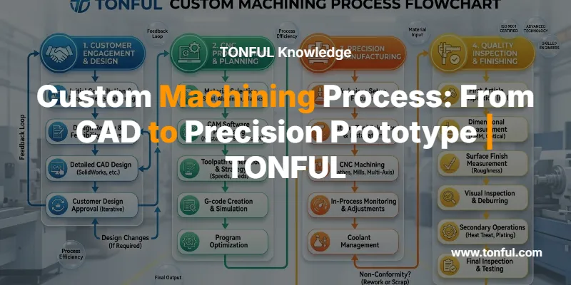
In today’s competitive manufacturing landscape, the journey from initial CAD drawing to finished prototype determines project success. At TONFUL Electric, our custom machining process combines precision engineering with decades of expertise in electrical components manufacturing to deliver prototypes that meet exact specifications. This comprehensive guide reveals the step-by-step workflow we use to transform digital designs into physical parts—ensuring quality, accuracy, and speed for B2B clients worldwide.

Understanding the Custom Machining Process
The custom machining process encompasses the complete workflow from digital design files to physical prototypes. For electrical component manufacturers like TONFUL, this process must balance tight tolerances with production efficiency. Modern CNC (Computer Numerical Control) machining allows us to produce custom CNC turning parts with tolerances as tight as ±0.005mm—critical for components like automotive terminals and PCB connectors.
The process begins when engineers upload CAD files and ends with fully inspected, production-ready prototypes. Each stage involves specific technologies, quality checkpoints, and material considerations that directly impact the final product’s performance.
Stage 1: CAD File Reception and Design Review
File Format Compatibility
Our engineering team accepts multiple CAD formats to accommodate diverse client workflows:
| File Format | Extension | Best Use Case | Compatibility Level |
|---|---|---|---|
| STEP | .stp, .step | Universal standard, maintains 3D geometry | Excellent |
| IGES | .igs, .iges | Legacy systems, surface data | Good |
| Parasolid | .x_t, .x_b | High-precision solid models | Excellent |
| SOLIDWORKS | .sldprt | Native SOLIDWORKS users | Excellent |
| AutoCAD | .dwg, .dxf | 2D drawings, sheet metal | Good |
Design for Manufacturability (DFM) Analysis
Upon receiving your CAD files, our engineers conduct a thorough DFM review to identify potential manufacturing challenges before machining begins. This critical step prevents costly revisions and ensures your custom machined parts can be produced efficiently.
Key DFM Checkpoints:
- Wall thickness verification: Minimum 0.5mm for aluminum, 0.8mm for stainless steel
- Corner radius optimization: Internal corners require minimum R0.3mm for tool access
- Tolerance rationalization: Identifying which dimensions truly require tight tolerances
- Material selection validation: Confirming material choice matches application requirements (see our SS304 vs SS316 guide)
- Undercut detection: Flagging features requiring special tooling or multi-axis machining

Stage 2: CAM Programming and Toolpath Generation
Converting CAD to Machine Instructions
Computer-Aided Manufacturing (CAM) software translates 3D CAD models into G-code—the numerical language CNC machines understand. Our programmers use advanced CAM systems to optimize cutting strategies for each unique part geometry.
CAM Programming Considerations:
| Factor | Impact on Machining | TONFUL Optimization Strategy |
|---|---|---|
| Cutting speed | Surface finish, tool life | Material-specific feed rate databases |
| Tool selection | Accuracy, cycle time | 200+ tool library with specialized geometries |
| Coolant strategy | Heat management, chip evacuation | High-pressure through-tool coolant systems |
| Fixture design | Part stability, access | Custom soft jaws for complex geometries |
| Multi-axis coordination | Complex features, undercuts | 5-axis simultaneous machining capability |
Simulation and Collision Detection
Before any metal is cut, our CAM software simulates the entire machining process virtually. This digital validation identifies potential collisions between cutting tools, fixtures, and the workpiece—preventing expensive machine crashes and scrapped parts.
Stage 3: Material Selection and Preparation
Choosing the right material is crucial for prototype success. At TONFUL, we stock a comprehensive range of materials suitable for electrical components:
Common Materials for Electrical Component Prototypes
| Material | Typical Applications | Machinability Rating | Key Properties |
|---|---|---|---|
| Brass (C36000) | Terminals, inserts | Excellent (90/100) | High conductivity, corrosion resistance |
| Copper (C11000) | Bus bars, heavy-duty lugs | Good (70/100) | Maximum conductivity, soft |
| Stainless Steel 304 | Connector housings, brackets | Good (65/100) | Corrosion resistant, non-magnetic |
| Stainless Steel 316 | Marine applications, harsh environments | Fair (55/100) | Superior corrosion resistance |
| Aluminum 6061-T6 | Lightweight housings, heat sinks | Excellent (85/100) | Lightweight, good strength-to-weight |
| PEEK | High-temperature insulators | Fair (50/100) | 260°C continuous, excellent dielectric |
For specialized applications, we also machine custom pneumatic fittings and precision fasteners. Material certification documents (mill test reports) are provided with every prototype shipment.

Stage 4: Precision CNC Machining Operations
Multi-Axis Machining Capabilities
TONFUL’s machining center features state-of-the-art CNC equipment capable of producing complex geometries in a single setup:
- 3-axis CNC milling: Standard operations for flat and simple contoured parts
- 4-axis indexed milling: Rotary axis for cylindrical features and multiple-sided machining
- 5-axis simultaneous machining: Complex angles, undercuts, and organic shapes
- CNC turning: Cylindrical parts, threads, and precision bores
- Swiss-type turning: Small-diameter, high-precision pins and shafts
Tolerance Capabilities and Standards
Achieving consistent tolerances requires environmental control, calibrated equipment, and skilled operators. Our facility maintains 20°C ±2°C temperature control in the machining area to prevent thermal expansion errors.
TONFUL Standard Tolerance Ranges:
| Feature Type | Standard Tolerance | Tight Tolerance | Ultra-Precision |
|---|---|---|---|
| Linear dimensions | ±0.1mm | ±0.05mm | ±0.01mm |
| Hole diameters | ±0.05mm | ±0.02mm | ±0.005mm |
| Thread pitch | ISO 2B/6H | ISO 2B/6g | ISO 3B/5g |
| Surface finish | Ra 3.2μm | Ra 1.6μm | Ra 0.4μm |
| Perpendicularity | 0.1mm/100mm | 0.05mm/100mm | 0.01mm/100mm |
| Concentricity | 0.05mm | 0.02mm | 0.01mm |
These tolerances align with international standards and exceed typical requirements for automotive connectors and industrial terminals.

Stage 5: Quality Control and Inspection
Multi-Stage Inspection Protocol
Every prototype undergoes rigorous inspection at multiple process stages:
First Article Inspection (FAI): Complete dimensional verification of the first machined part against CAD specifications using our Zeiss CMM (Coordinate Measuring Machine) with 2μm accuracy.
In-Process Inspection: Operators verify critical dimensions every 10 parts (or hourly for long runs) using calibrated micrometers, height gauges, and optical comparators.
Final Inspection: 100% visual inspection plus dimensional verification of all critical features. Parts receive individual inspection reports with actual measured values.
Inspection Equipment and Capabilities
| Equipment Type | Model/Capability | Measurement Range | Accuracy |
|---|---|---|---|
| CMM (Coordinate Measuring Machine) | Zeiss Contura G2 | 700×1000×600mm | ±2μm |
| Optical Comparator | Nikon V-20B | 200mm diameter | ±3μm |
| Surface Roughness Tester | Mitutoyo SJ-410 | Ra 0.01-40μm | ±0.01μm |
| Digital Micrometers | Mitutoyo Quantumike | 0-300mm | ±1μm |
| Thread Gauges | GO/NO-GO sets | M1-M24, UNC/UNF | Per ISO 1502 |
| Hardness Tester | Rockwell/Vickers | HRC 20-70 | ±1 HRC |
This inspection infrastructure ensures every prototype meets specifications before shipment—critical for components like crimping terminals and automotive switches.
Stage 6: Surface Treatment and Finishing
Available Surface Finishes
Raw machined parts often require surface treatments to enhance corrosion resistance, appearance, or electrical properties:
- Electroplating: Tin, nickel, silver, or gold plating for electrical terminals
- Anodizing: Type II or Type III hard anodizing for aluminum components
- Passivation: Chemical treatment for stainless steel parts per ASTM A967
- Powder coating: Durable finish for housings and brackets
- Tumbling/deburring: Edge break and surface smoothing
- Laser marking: Permanent part identification and traceability

Stage 7: Prototype Delivery and Documentation
Complete Documentation Package
Each prototype shipment includes comprehensive documentation:
- Dimensional inspection report: Actual measured values vs. CAD specifications
- Material certification: Mill test reports with chemical composition and mechanical properties
- Surface finish verification: Ra measurements and coating thickness reports
- Photographic documentation: High-resolution images of finished parts
- Process traveler: Complete machining history and operator sign-offs
Lead Time and Pricing Factors
Typical Lead Times for Custom Machining:
| Complexity Level | CAD Review | Programming | Machining | Inspection | Total Lead Time |
|---|---|---|---|---|---|
| Simple (2D features) | 1 day | 1 day | 1-2 days | 1 day | 4-5 days |
| Moderate (3D features) | 1-2 days | 2 days | 2-3 days | 1 day | 6-8 days |
| Complex (5-axis required) | 2-3 days | 3-4 days | 3-5 days | 1-2 days | 9-14 days |
Cost Factors:
- Material type and availability
- Tolerance requirements (tighter = higher cost)
- Quantity (setup costs amortized over volume)
- Surface finish complexity
- Inspection requirements (standard vs. FAI with full CMM report)
For volume production following prototype approval, see our guide on HMLV wire harness manufacturing to understand how we scale from prototypes to production.
Why Choose TONFUL for Custom Machining
Integrated Manufacturing Ecosystem
Unlike standalone machine shops, TONFUL offers complete electrical component solutions under one roof. Our custom machining capabilities integrate seamlessly with our wire harness assembly, terminal manufacturing, and connector production services.
Key Advantages:
- Single-source convenience: Machined parts, terminals, and assemblies from one supplier
- Design optimization: Our engineers understand how machined components integrate with electrical systems
- Quality consistency: Unified quality standards across all manufacturing processes
- Cost efficiency: Eliminate markup from multiple vendors
- Faster time-to-market: Coordinated production scheduling across all component types
Industry Certifications and Standards
TONFUL maintains rigorous quality certifications:
- ISO 9001:2015 Quality Management System
- IATF 16949 Automotive Quality Standard
- RoHS and REACH compliance for all materials
- UL recognition for electrical components
Our conflict-free sourcing practices and halogen-free materials ensure your prototypes meet global regulatory requirements.
Frequently Asked Questions (FAQ)
Q: What file formats do you accept for custom machining projects?
A: We accept STEP, IGES, Parasolid, SOLIDWORKS, and AutoCAD formats. STEP (.stp) files are preferred as they maintain the most complete 3D geometry information across different CAD systems.
Q: What is the minimum order quantity for custom machined prototypes?
A: We accept orders starting from a single prototype piece. There is no minimum order quantity, making us ideal for R&D projects and low-volume specialty applications.
Q: How tight can your machining tolerances be?
A: Our standard capability is ±0.05mm for most features. For critical dimensions, we can achieve ±0.01mm or tighter using precision grinding and temperature-controlled machining. Tolerances depend on material, geometry, and feature size.
Q: Can you machine both metal and plastic materials?
A: Yes, we machine a wide range of materials including brass, copper, stainless steel, aluminum, and engineering plastics (PEEK, Delrin, Nylon). Material selection depends on your application requirements for conductivity, strength, and environmental resistance.
Q: Do you provide material certifications with prototypes?
A: Yes, every shipment includes material certifications (mill test reports) showing chemical composition and mechanical properties. We can also provide RoHS/REACH compliance documentation when required.
Q: What’s the typical lead time from CAD file to finished prototype?
A: Simple parts can be completed in 4-5 days, while complex multi-axis components may require 9-14 days. Rush services are available for urgent projects with 2-3 day turnaround for an additional fee.
Q: Can you help optimize my design for manufacturability?
A: Absolutely. Our engineering team provides complimentary DFM (Design for Manufacturability) analysis with every quote. We’ll identify potential issues and suggest modifications to improve quality and reduce costs before machining begins.
Q: How do you ensure consistent quality across multiple prototype iterations?
A: We use CMM (Coordinate Measuring Machine) inspection with 2μm accuracy, maintain detailed process documentation, and store proven CAM programs for repeat orders. Every part receives an inspection report with actual measured dimensions.
Conclusion: Precision Machining for Electrical Excellence
The custom machining process transforms digital concepts into physical reality through careful planning, advanced technology, and rigorous quality control. At TONFUL Electric, our integrated approach combines precision machining with deep electrical component expertise—ensuring your prototypes not only meet dimensional specifications but also perform flawlessly in their intended applications.
Whether you need custom dowel pins, machined connector housings, or specialized fasteners, our CAD-to-prototype process delivers the precision and reliability your projects demand.
Ready to transform your CAD designs into precision prototypes? Contact TONFUL Electric today to discuss your custom machining requirements. Our engineering team is ready to review your designs, provide DFM feedback, and deliver prototypes that exceed expectations.
TONFUL Electric: Your trusted partner for custom electrical components, precision machining, and integrated manufacturing solutions since 1998.