
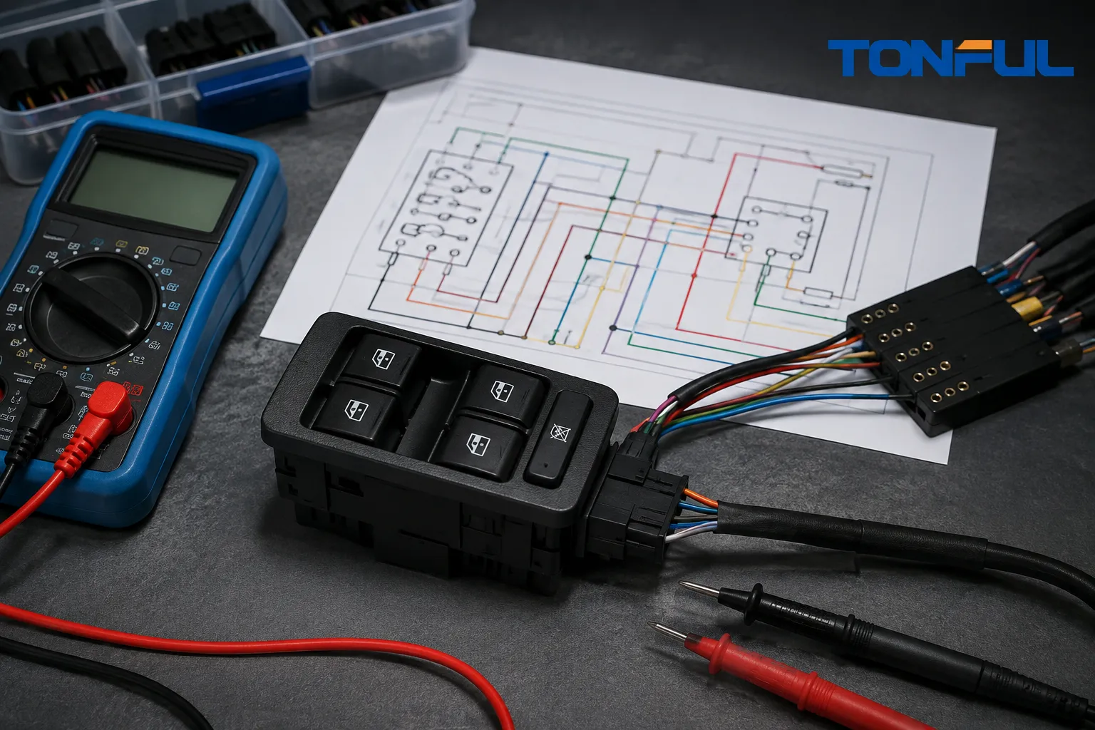
Testing a power window switch is not a matter of probing random terminals until a meter changes. Some switches carry motor current, some create resistance-coded commands, and others communicate with a door module. Applying power to the wrong pin can damage electronics, create a short circuit, or move the glass unexpectedly.
The safe method begins with the exact vehicle wiring diagram, connector view, diagnostic procedure, and switch architecture. This guide provides a repeatable workflow and record format, but it does not provide a universal pinout or acceptance value. Use the vehicle manufacturer’s current service information for every connection and limit.
Safety and Tools
Prevent glass movement from trapping fingers, tools, or wiring. Support loose glass and door components as required. Follow battery-disconnection, airbag, retained-accessory-power, anti-pinch, and initialization procedures. Never bypass circuit protection or use a high-current jumper on an unknown circuit.
Useful equipment may include a digital multimeter with suitable category, range, resolution, and accuracy; fused test leads; back-probes or an approved breakout harness; wiring diagrams and connector views; a scan tool for module-controlled systems; and basic trim tools. Use terminal test adapters that do not spread or damage female contacts. A test light may load circuits differently from a high-impedance meter and should be used only where the procedure permits it.
Before measuring resistance, isolate power as instructed. Before measuring voltage, confirm the meter function and lead ports. Inspect lead condition and perform meter zero or lead compensation when the specified method requires it. The NHTSA-hosted Toyota master-switch inspection instructions specifically require DVOM zero calibration and controlled probe contact for its resistance checks, demonstrating why method details matter.
Identify the Circuit Architecture
Determine whether the switch directly controls the motor, commands relays, creates resistance values, or communicates electronically. Review power, ground, ignition or accessory feeds, illumination, lockout, motor outputs, module connections, and network lines. Record connector orientation and whether the diagram shows the component side or harness side.
A direct switch may reverse polarity to the motor. A resistance-coded switch may produce different values for up, down, and neutral. An electronic master unit may require scan data or a specified output test rather than an ohmmeter. TONFUL’s automotive PCB connector guide explains several connector and signal-integrity considerations that also matter when a switch contains electronics.
Step-by-Step Power Window Switch Test

Conceptual test flow—values and pinouts are vehicle-specific.
1. Confirm the Complaint
Operate every window from the master and local controls under the conditions specified by the vehicle. Record direction, manual or automatic stage, window lock, door lock, illumination, temperature, door position, and intermittent behavior. Check whether one window or every window is affected. Do not repeatedly cycle a binding or tilted glass.
2. Check Service Information and DTCs
Read system descriptions, DTCs, initialization status, fail-safe behavior, and technical bulletins. A module-controlled system may disable automatic movement after battery disconnection or store a fault for motor position, overcurrent, communication, or power supply. Diagnose those conditions before removing the switch.
3. Inspect the Switch and Connector
Look for cracked or sticky rockers, weak return, contamination, liquid residue, corrosion, discoloration, overheated terminals, loose retention, pushed-back terminals, damaged seals, bent pins, and harness damage at the door hinge. Photograph findings before cleaning or disconnecting intermittent components.
Connector condition matters because a good switch cannot overcome an open, high-resistance, or poorly retained terminal. TONFUL’s terminal push-out-force guide explains why terminal retention is a separate control from electrical continuity.
4. Verify Power and Ground
Using the named test points and conditions in service information, check each required supply and ground. Test grounds under the specified load or use the approved voltage-drop method when required. Battery voltage measured somewhere else does not prove the switch receives adequate voltage under load. If power or ground is missing, diagnose the fuse, relay, harness, connector, splice, module, or ground path before condemning the switch.
5. Check Switch Inputs and Outputs
Back-probe only where permitted and avoid piercing insulation unless the repair procedure allows and restores it. Operate each rocker through neutral, manual, and automatic stages while observing the specified voltage, continuity, resistance, or scan-data state. Record actual readings and the acceptance-source document.
For direct motor control, compare both directions and polarity behavior. For resistor-coded controls, compare every switch position with the exact chart. For networked switches, verify power, ground, communication, DTCs, and command states using the specified equipment. Do not use a continuity beep as the only evidence when the procedure requires measured resistance, voltage under load, or module data.
The Stellantis master-switch service instruction provides an example of checking physical condition and vehicle-specific internal resistor values. Its numbers belong to that application only.
6. Confirm the Downstream Circuit
If switch behavior matches specification but the window does not move, check command arrival at the motor or door module. Verify harness continuity and short-to-ground/voltage tests according to the diagram. Evaluate the motor, regulator, glass alignment, and mechanical drag. The Power Window Switch vs Motor vs Regulator fault guide provides a structured component-level isolation path for this stage. Do not direct-power an integrated electronic motor unless specifically authorized.
7. Verify the Repair
After repair, reconnect and secure all components, restore seals and trim, clear DTCs where appropriate, and perform required initialization. Test every window from every control, manual and automatic stages, lockout, retained operation, illumination, and anti-pinch or reversal functions under the approved procedure.
Resistance, Voltage, and Signal Tests
Resistance tests require an unpowered and appropriately isolated circuit. Document meter range, lead compensation, test-point orientation, switch position, ambient condition, reading, and limit. Very low contact resistance may need a controlled method beyond a handheld continuity function. TONFUL’s automotive combination-switch contact-resistance testing guide covers four-wire measurement concepts for product validation; field service procedures may specify a different method.
Voltage testing should record battery condition, ignition mode, connector state, load, reference ground, and switch position. An unloaded voltage can appear normal through a high-resistance path, so follow the service procedure’s load or voltage-drop test. Never short adjacent terminals with an oversized probe.
Signal testing may involve resistor ladders, pulse-width signals, LIN/CAN communication, or module scan data. Use an oscilloscope or scan tool only when the procedure calls for it and the operator understands reference ground, bandwidth, probe loading, and expected behavior. A fluctuating signal is not automatically a bad switch; module logic and network conditions matter.
Interpreting Results
| Evidence | Likely next action |
|---|---|
| Required supply or ground missing | Diagnose upstream circuit before switch replacement |
| Physical rocker fails to return or sticks | Confirm mechanical defect and inspect contamination/damage |
| Correct input, incorrect specified output in one position | Confirm connector/test setup, then evaluate switch replacement |
| Switch data changes correctly but motor command is absent | Diagnose module logic, lockout, communication, or harness |
| Correct motor command present but no movement | Test motor, regulator, glass load, and downstream connections |
| Fault disappears when harness moves | Preserve position and inspect terminals, flex harness, and connector retention |
These are routing decisions, not universal pass/fail rules. A replacement decision requires agreement between observed symptom, verified inputs, measured switch behavior, downstream response, and service-information criteria.
Power Window Switch Test Record

Conceptual record template—follow the approved diagnostic procedure.
| Record field | Entry |
|---|---|
| Vehicle/VIN, model year, trim, door position | |
| Switch part number and revision | |
| Complaint and operating conditions | |
| Service document, diagram, connector view, revision | |
| Meter/tool ID, range, accuracy, lead check | |
| Battery/ignition condition | |
| Connector and terminal inspection | |
| Test point and connector orientation | |
| Switch position and expected behavior | |
| Actual voltage/resistance/signal or scan state | |
| Motor/regulator response | |
| DTCs and initialization status | |
| Pass/fail, root cause, repair, technician/date |
Store photos and scan reports under the same job or sample ID. If a test is invalid because of the wrong connector orientation, unstable probe contact, incorrect meter function, or unmet precondition, document it and repeat under the approved method rather than hiding the first result.
Testing Parts for Sourcing and Quality Approval
Field diagnosis confirms a vehicle repair; supplier validation proves a product design and process under defined conditions. For incoming or qualification testing, identify sample quantity, part and material lots, fixture, electrical load, actuation rate, environment, acceptance criteria, invalid-test handling, traceability, and report approval. Include every switch position and function.
Control the Measurement System
A pass/fail record is credible only when the measurement system is suitable for the requirement. Record the instrument ID, calibration status, range, resolution, fixture or breakout harness, software version where applicable, ambient condition, operator, and test date. Verify lead compensation or meter zeroing before low-resistance work, and document whether readings are taken at component terminals, harness terminals, or module data points. Never compare results collected from different points as though they were equivalent.
For repeated production inspection, assess fixture contact wear, connector mating cycles, terminal damage, operator technique, and repeatability. A reference sample or controlled check can reveal drift before good parts are rejected or defective parts accepted. If a reading is unstable, preserve the initial result, identify the reason for invalidation, and repeat only under the written retest rule.
The final report should link every limit to a drawing, customer specification, approved control plan, or vehicle service document. It should also identify sample disposition and corrective action. TONFUL’s PA66 versus ABS automotive material guide provides useful background when heat, housing deformation, or material selection is part of the investigation, but application approval still depends on the actual product specification.
TONFUL’s Power Window Switch Manufacturer product page presents current vehicle applications and OE reference numbers. Confirm the exact vehicle, OE reference, connector, pinout, functions, approved sample, and project-specific validation plan before ordering.
Share the vehicle application, OE reference, connector and pinout, approved sample, circuit diagram, expected functions, measurements, forecast, and validation plan with TONFUL for power window switch sourcing and technical review. Do not use a universal pinout, resistance, voltage, current, or durability limit unless it is supported by product-specific documentation.
Related TONFUL Automotive Guides
- Use the Power Window Switch vs Motor vs Regulator fault guide to isolate the failed component before performing detailed switch measurements.
- Review Automotive Combination Switch Contact Resistance Testing for controlled low-resistance measurement principles and evidence fields.
- Consult the Automotive PCB Connectors Guide when electronic architecture, connector interfaces, or signal integrity affects the diagnosis.
- Use Terminal Push-Out Force for Automotive Connectors when a backed-out or poorly retained terminal may interrupt the circuit.
- Compare PA66 vs ABS Automotive Connector Materials when housing deformation, heat, or material requirements are part of the failure review.