
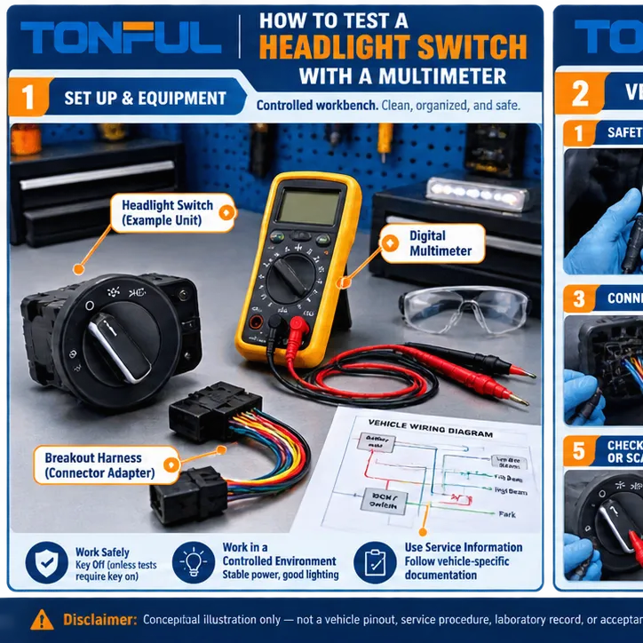
A multimeter can help confirm a headlight-switch fault, but only after the circuit architecture, connector orientation, and vehicle-specific test points are identified. Headlight controls range from current-carrying rotary switches to relay triggers, switched-ground circuits, resistance-coded inputs, and low-current requests interpreted by a body control module (BCM). The wrong test method can produce a false diagnosis or damage a module.
Begin with the exact complaint. If the lamps are dark, intermittent, limited to one function, hot at the connector, or incorrect only in AUTO mode, use the Bad Headlight Switch Symptoms and Diagnosis guide to separate likely switch faults from bulb, fuse, relay, ground, connector, sensor, and BCM problems. Then use the procedure below to test the identified circuit rather than guessing from switch appearance.
TONFUL’s headlight switch range presents current vehicle applications and OE reference numbers. Confirm the exact vehicle, OE reference, connector, pinout, functions, approved sample, and project-specific validation plan before ordering. This guide does not create a universal pinout, voltage, resistance, current, durability limit, or vehicle repair procedure. Use current service information, drawings, customer specifications, and approved test plans.
Quick Evidence Framework

Conceptual illustration only—not a vehicle-specific fitment record, diagnosis, wiring diagram, laboratory record, or acceptance standard.
| Decision area | Evidence to retain | Common error | Release rule |
|---|---|---|---|
| 1. Start With the Vehicle Diagram | Identify direct-load, relay-controlled, ground-side, resistance-coded, or BCM/network architecture before probing. | The same knob positions can produce current outputs, grounds, resistance values, or digital requests depending on the vehicle. | Record connector orientation and whether the drawing shows harness side or component side. |
| 2. Prepare Safely | Follow battery, airbag, trim-removal, retained-power, lighting, and module procedures; protect probes from accidental shorts. | An unfused jumper or wrong meter range can damage wiring, modules, or switch contacts. | Use approved back-probing tools or a breakout harness and never pierce insulation unless the repair procedure permits restoration. |
| 3. Inspect Before Measuring | Check rocker or rotary feel, contamination, corrosion, pushed-back terminals, latch damage, heat discoloration, melted plastic, and harness strain. | Disconnecting or cleaning an intermittent connector can erase evidence. | Photograph the condition and record terminal retention before disturbing it. |
| 4. Verify Supply and Ground | Measure the named supplies and grounds under the conditions and load specified by service information. | Open-circuit battery voltage does not prove the path can carry current; excess resistance may appear only under load. | Use approved voltage-drop testing and compare actual values only with the vehicle specification. |
| 5. Test Switch States and Outputs | Operate every position while observing the specified continuity, resistance, voltage, ground, scan-data state, or network response. | A continuity beep is insufficient for low-resistance characterization and must never be used on a powered circuit. | Record actual values, meter settings, test points, lead check, and acceptance source. |
| 6. Confirm the Downstream Circuit and Repair | If the switch state is correct, verify relay, BCM or driver command, fuses, harness, grounds, lamp connectors, and lamp load. | A good switch cannot overcome a burned relay contact, module fault, poor ground, or overheated socket. | Restore connectors and trim, clear DTCs where appropriate, and test every lighting position after repair. |
The table is a routing tool rather than proof that a switch passes. Every approval should identify the vehicle or product, sample, source document, revision, reviewer, date, and unresolved conditions. Unknown information must remain Unknown until verified.
Start With the Vehicle Diagram
Obtain the wiring diagram, connector view, system description, fuse and relay locations, and test procedure for the exact vehicle, market, production date, and equipment level. Determine whether the switch carries lamp current, switches a relay coil, completes a ground path, presents coded resistance to a module, or sends a network request. This decision controls whether you should measure continuity, resistance, voltage, voltage drop, or scan data.
Confirm drawing orientation before identifying a cavity. A connector illustration may show the harness face, terminal face, or component side, and the numbering direction can reverse when viewed from the opposite end. Compare cavity numbers, keyways, latch position, wire colors, and populated terminals. Mark the drawing you actually used and photograph the connector in the same orientation.
Create a function matrix for OFF, parking lamps, low beam, AUTO, front or rear fog lamps, dimmer, illumination, and leveling functions where fitted. For each position, list the expected input, output, ground, resistance band, or module state from the service information. If the OE reference, connector, or architecture does not match, stop before probing and resolve the application through the Headlight Switch Buying Guide.
Prepare Safely
Follow the vehicle procedure for battery isolation, retained accessory power, airbag-adjacent trim, module wake-up, and reconnect initialization. Some switch tests require the circuit powered; others require complete isolation. Never use resistance or continuity mode on an energized circuit. Do not substitute an unfused jumper for a meter test, because a mistaken cavity can short a module output or overheat a small signal contact.
Use a meter with suitable category, range, input protection, and verified leads. Inspect the lead insulation and tips, select the correct input sockets, and check the meter on a known source before and after a voltage test. For low-resistance work, short the leads together and record lead resistance or use the compensation function when the approved method permits it. A continuity beeper is a quick state indicator, not a universal contact-resistance acceptance test.
Prefer an approved breakout harness or terminal-compatible back-probe. Oversize probes can spread female terminals and create the intermittent fault being investigated. Avoid piercing insulation unless the repair procedure authorizes it and defines sealing afterward. Secure loose probes so they cannot bridge adjacent cavities when the knob is operated.
Inspect Before Measuring
Preserve intermittent evidence before unplugging anything. Operate the rotary or rocker control through every detent and note looseness, sticking, missed positions, abnormal return, or a complaint that changes when the knob or harness moves. Record whether the fault depends on temperature, vibration, moisture, lamp warm-up time, or trim-panel pressure.
Inspect the switch body and mating connector for contamination, corrosion, fretting, pushed-back terminals, weak retention, damaged locks, wire strain, discoloration, odor, softened plastic, and previous repairs. Photograph the connector face and affected cavity before cleaning. If heat damage is present, stop repeated operation and inspect both mating components, the specified lamp load, fusing, grounds, relay path, and downstream wiring; replacing only the switch may leave reduced terminal grip or excessive current unresolved.
Compare terminal population and wire colors with the diagram. A missing terminal may be normal for an option level, while an added repair wire may indicate a previous modification. Record physical findings separately from electrical readings so later reviewers can connect a voltage-drop result to a specific cavity and condition.
Verify Supply and Ground
Set the meter to DC voltage and verify the supply at the named switch cavity under the key, lamp, and load conditions specified by the vehicle procedure. Measure battery voltage at the same time if the diagnosis depends on a comparison. An open-circuit reading near battery voltage does not prove that a corroded feed can carry operating current.
For a loaded power-side voltage-drop test, place the probes across the portion of the active path being evaluated, such as battery positive to switch supply or across a closed switch contact when the architecture permits. For the ground side, measure between the circuit ground point and battery negative while the relevant load operates. Probe polarity affects the sign, not the magnitude, but consistent orientation makes records easier to compare.
Use only vehicle-specific limits and test conditions. Record the circuit state, load, probe locations, battery voltage, measured drop, meter range, and source document. Fluke’s automotive troubleshooting guide explains voltage-drop test principles. Use it for measurement method, not as a source of vehicle-specific limits or switch pinouts.
Test Switch States and Outputs
Choose the test by architecture. For an isolated mechanical contact, disconnect power and any module path, identify the specified terminal pair, and measure continuity or resistance through every relevant position. Record the actual value rather than only “beep/no beep.” Move the control slowly through each detent and watch for unstable readings that correspond with the complaint.
For a powered relay-trigger or switched-ground circuit, back-probe the specified input and output without loading a signal line beyond the approved method. Confirm both the available input and the change at the output when the switch moves. For a resistance-coded BCM input, compare measured values or scan states with vehicle data; do not assume another model’s resistor ladder applies. For a networked control, a multimeter may verify supply and ground, but state interpretation may require a scan tool.
Complete a row for every switch position: connector and cavity pair, meter mode and range, lead compensation, switch state, expected result and source, actual result, stability, and pass/fail decision. If one channel fails, repeat only after checking probe contact and test setup. Do not average an intermittent open into an acceptable reading or invent a universal resistance threshold.
Confirm the Downstream Circuit and Repair
If the switch produces the correct state, follow the signal downstream instead of replacing it. In a relay-controlled system, verify coil command, relay ground, contact feed, and loaded output. In a BCM-controlled system, compare physical position with scan-data input, commanded output, enabling conditions, DTCs, sensor data, and vehicle configuration. At the lamp side, inspect fuses, grounds, sockets, bulbs or LED drivers, connector heat, and harness voltage drop.
If the switch output is wrong, verify that its supply, reference, ground, connector contact, and mechanical position were correct during the test. An unstable reading that changes when the harness moves may identify a terminal or wire fault rather than an internal switch contact. The Automotive Combination Switch Contact Resistance Testing guide provides additional measurement-control principles, while the headlight-switch drawing remains the acceptance source for this product.
After repair, restore connector locks, routing, seals, trim, and battery procedures. Clear DTCs only after saving the original record when the service process calls for it. Verify manual and automatic lighting functions, switch illumination, dimming, fog lamps, high beam, and any retained or welcome-light behavior fitted to the vehicle. Record the root cause, parts changed, final measurements, unresolved conditions, technician, and date.
A Controlled Workflow

This conceptual workflow organizes evidence; it does not replace the applicable vehicle procedure or product specification.
- Define the complaint, sourcing question, application, and exact function under review.
- Identify the vehicle, market, production range, switch location, OE reference, and supersession status.
- Obtain the wiring diagram, connector view, system description, service instructions, and safety precautions.
- Inspect the switch, connector, terminals, harness, related control devices, and lamp-side components before disturbing intermittent evidence.
- Perform only authorized measurements with suitable calibrated equipment, protected probes, and controlled test conditions.
- Compare actual results with a named acceptance source; do not import values from another vehicle.
- Confirm the downstream response and root cause before replacing or approving a switch.
- Record repair or sample disposition, final functional verification, approver, date, and future change controls.
This workflow preserves the distinction between a measurement method and an acceptance requirement. Meter guidance can explain how to measure; only the applicable vehicle information, approved drawing, product specification, or customer test plan should define the result required for the specific switch and circuit.
Sourcing and Change Control
For a quotation, provide the complete OE reference, vehicle and market, switch location and type, front and connector-end photos, dimensions, terminal population, functions, symbols, illumination, expected architecture, forecast, packaging, and required validation. The Headlight Switch Manufacturer product page is the correct commercial destination for current TONFUL headlight switch applications and OE references. Final compatibility should be tied to an approved sample and project record.
Request controlled drawings, function matrices, sample IDs, inspection reports, test plans, raw-data references, packaging approval, lot traceability, nonconformance handling, and change notification. Material, contact, plating, spring, PCB, software where present, tooling, process, sub-supplier, site, artwork, and test-method changes may alter performance or fit. Define which changes require notice and reapproval.
The H4 vs H11 Headlight Socket Guide helps separate a lamp-socket or connector problem from a switch complaint, while the Wiper Switch Failure Symptoms Guide demonstrates an evidence-first approach for another automotive switch. These related pages should support diagnosis, not encourage parts swapping.
For application selection before testing or ordering, review the Headlight Switch Buying Guide. For symptom-led fault isolation, use Bad Headlight Switch Symptoms and Diagnosis. These pages form a sequence from fitment and symptom classification to controlled measurement.
Final Release Checklist
- The exact vehicle, market, production range, door or dashboard location, and OE chain are recorded.
- Switch type, mounting, symbols, connector keying, terminals, and every function are confirmed.
- Electrical architecture is identified before continuity, voltage, resistance, scan-data, or load testing.
- Inspection includes the mating connector, terminals, wiring, controls, grounds, and lamp-side components.
- Measurements include instrument, range, probes, test points, conditions, actual result, and acceptance source.
- No universal pinout, limit, jumper, compatibility, certification, or lifetime claim is used without product-specific evidence.
- The approved sample, packaging, labels, traceability, and change-notification responsibilities are controlled.
- Final operation is verified across every relevant switch position and system mode.
Work With TONFUL
Send TONFUL the vehicle application, full OE reference and supersession information, clear front and connector-end photographs, switch type, functions, symbols, pinout source, required tests, annual demand, destination market, and packaging needs. TONFUL can review the headlight switch request against current applications and OE references, then align sample and validation requirements for the project. Do not assume that relays, BCMs, lamp assemblies, or unrelated lighting components are included in the headlight switch range unless they are separately documented and agreed.
