
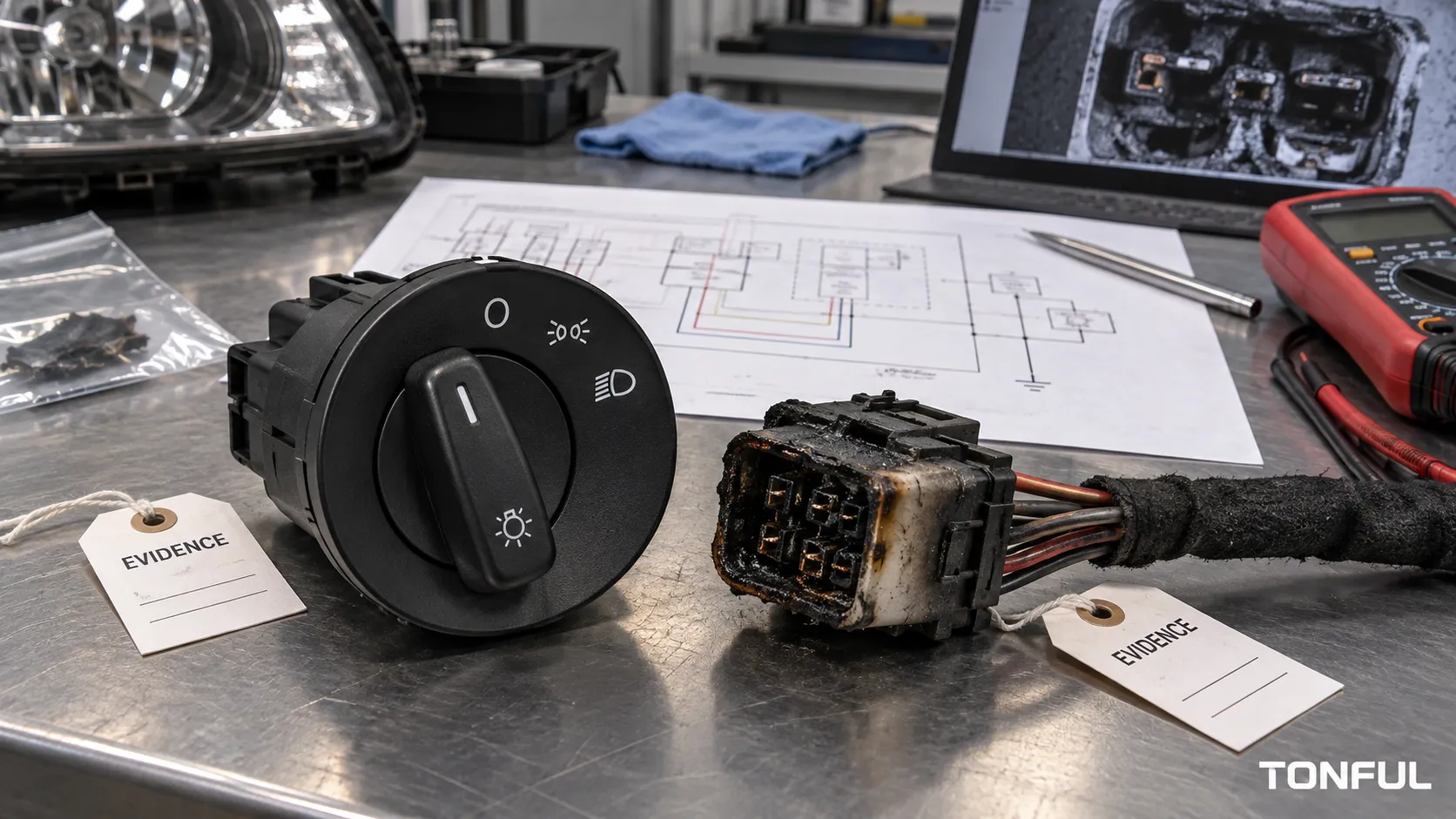
A melted headlight switch or connector is evidence of heat, not a complete root-cause diagnosis. Heat may develop from resistance at a contact or terminal, excessive circuit current, an incorrect lamp load, damaged crimps, poor repairs, connector movement, contamination, or a control architecture operating outside its intended design. Replacing only the visibly burned part can recreate the failure.
TONFUL’s current headlight-switch range presents vehicle applications and OE references. Confirm the exact vehicle, complete OE reference, connector, pinout, functions, approved sample and project-specific validation plan before ordering or testing.
Quick Evidence Matrix

Conceptual illustration only – not a vehicle procedure, laboratory result, universal limit, or acceptance standard.
| Work area | Required focus | Acceptance source |
|---|---|---|
| High Resistance at Switch Contacts | Observable evidence can include local heat, discoloration, unstable lighting and voltage loss across a closed contact. | Project specification, approved plan, or root-cause evidence |
| Low Terminal Grip or Mating Damage | A spread, backed-out, corroded or fretted terminal reduces effective contact area and can heat both connector and switch. | Project specification, approved plan, or root-cause evidence |
| Crimp, Wire or Repair Defects | Cut strands, loose crimps, conductor corrosion, undersized repair wire and poorly executed splices can concentrate resistance. | Project specification, approved plan, or root-cause evidence |
| Excess Current or Incorrect Lamp Load | Higher-than-approved current can overheat a sound interface. | Project specification, approved plan, or root-cause evidence |
| Harness Strain, Vibration and Poor Support | Connector movement, tight routing or unsupported mass can reduce contact stability and damage crimps or latches. | Project specification, approved plan, or root-cause evidence |
| Moisture, Contamination and Housing Damage | Water, salts, chemicals, dust and damaged seals can corrode contacts and alter insulation or terminal force. | Project specification, approved plan, or root-cause evidence |
The matrix defines evidence categories, not pass values. Unknown requirements must remain open until the document owner confirms them.
High Resistance at Switch Contacts
Observable evidence can include local heat, discoloration, unstable lighting and voltage loss across a closed contact. Contain the vehicle or lot, preserve the switch position and load condition, then compare loaded drop, contact condition and thermal evidence. Confirm with controlled measurements or teardown; correct the contact design, contamination or wear mechanism and update monitoring.
Record the applicable component, circuit or sample identity and retain objective evidence. Where a numeric requirement is needed, cite the product drawing, OEM/customer specification, qualification plan or approved test procedure rather than supplying a generic value.
Low Terminal Grip or Mating Damage
A spread, backed-out, corroded or fretted terminal reduces effective contact area and can heat both connector and switch. Photograph before disconnecting, check retention and mating surfaces, and inspect both halves. Replace all heat-damaged mating parts required by the repair, correct terminal selection or insertion, and add retention and connector inspection controls.
Record the applicable component, circuit or sample identity and retain objective evidence. Where a numeric requirement is needed, cite the product drawing, OEM/customer specification, qualification plan or approved test procedure rather than supplying a generic value.
Crimp, Wire or Repair Defects
Cut strands, loose crimps, conductor corrosion, undersized repair wire and poorly executed splices can concentrate resistance. Quarantine previous repairs, record wire and terminal identity, measure the suspect path under load and use cross-section or pull evidence when required. Correct the repair process and update tooling, inspection and technician authorization.
Record the applicable component, circuit or sample identity and retain objective evidence. Where a numeric requirement is needed, cite the product drawing, OEM/customer specification, qualification plan or approved test procedure rather than supplying a generic value.
Excess Current or Incorrect Lamp Load
Higher-than-approved current can overheat a sound interface. Record lamp or driver type, modifications, fuse rating, current waveform, downstream shorts and accessory wiring. Confirm against the vehicle specification rather than appearance. Restore the approved load and protection, repair shorts, and prevent uncontrolled substitutions.
Record the applicable component, circuit or sample identity and retain objective evidence. Where a numeric requirement is needed, cite the product drawing, OEM/customer specification, qualification plan or approved test procedure rather than supplying a generic value.
Harness Strain, Vibration and Poor Support
Connector movement, tight routing or unsupported mass can reduce contact stability and damage crimps or latches. Evidence includes position-sensitive flicker, fretting and strain marks. Reproduce only under controlled conditions, then correct routing, retention and support and add installation checks to the control plan.
Record the applicable component, circuit or sample identity and retain objective evidence. Where a numeric requirement is needed, cite the product drawing, OEM/customer specification, qualification plan or approved test procedure rather than supplying a generic value.
Moisture, Contamination and Housing Damage
Water, salts, chemicals, dust and damaged seals can corrode contacts and alter insulation or terminal force. Preserve residue for investigation, inspect seals and ingress paths, and distinguish initiating contamination from heat-created damage. Correct sealing, materials, handling or enclosure design according to the applicable environment specification.
Record the applicable component, circuit or sample identity and retain objective evidence. Where a numeric requirement is needed, cite the product drawing, OEM/customer specification, qualification plan or approved test procedure rather than supplying a generic value.
Test or Investigation Record

This conceptual record layout supports traceability; it does not replace the controlled test or investigation form.
Use a record with these fields:
| Sample/Vehicle ID | Symptom | Switch Position/Load | Cavity/Component | Visual/Thermal Evidence | Current | Loaded Voltage Drop | Terminal Retention | Crimp/Wire Result | Root-Cause Confirmation | Immediate Containment | Permanent Action | Control-Plan Change | Acceptance Source | Owner/Date |
|---|---|---|---|---|---|---|---|---|---|---|---|---|---|---|
| Complete for each sample or affected path | Enter controlled result | Enter controlled result | Enter controlled result | Enter controlled result | Enter controlled result | Enter controlled result | Enter controlled result | Enter controlled result | Enter controlled result | Enter controlled result | Enter controlled result | Enter controlled result | Enter controlled result | Enter controlled result |
Define sample quantity, conditioning, equipment range and accuracy, fixtures, test sequence, monitoring interval, invalid-test rules, retest authority, acceptance source and data retention before execution. Preserve raw readings and photographs; a summary pass/fail field cannot replace the evidence.
Internal Links and Decision Path
- TONFUL Headlight Switch Manufacturer
- Headlight Switch, Relay or BCM Control Guide
- Headlight Switch Multimeter Test
- Bad Headlight Switch Symptoms
- Headlight Switch Buying Guide
Use the architecture guide before choosing test points, the multimeter guide for safe field measurements, the symptoms guide for fault routing, and the buying guide for fitment evidence. These pages support different decisions and should not be treated as interchangeable procedures.
Supplier, Release, and Change Control
For an RFQ or validation request, provide vehicle, market, production range, OE chain, connector views, mounting, terminal population, function matrix, architecture, load or signal definition, environment, sample quantity, test plan, acceptance sources, annual demand, packaging and traceability needs. Request controlled drawings, raw-data references, nonconformance handling and change notification.
Receiving inspection should compare labels, lot identity, housing, connector, terminals, functions and packaging with the approved sample. Define reaction plans for discrepancies. Changes to contacts, plating, terminals, springs, resistor networks, electronics, LEDs, housing, tooling, process, sub-suppliers or manufacturing site may require notice and reapproval.
Final Release Checklist
- Scope, application, part revision, sample quantity and lot are identified.
- Electrical architecture, functions, loads, environment and conditions are documented.
- Equipment, fixtures, probes, ranges, accuracy and calibration status are recorded.
- Actual results, failure modes, photographs and raw-data references are retained.
- Every limit points to an approved source; no universal value is invented.
- Invalid tests, retests, deviations and unresolved items have documented disposition.
- Approved sample, receiving controls, traceability and change notification are defined.
- Release identifies reviewer, date, approved scope and closure evidence.
Planning Review Before Execution
Hold a cross-functional review with design, quality, test, manufacturing and customer representatives where required. Confirm that the fixture does not change the intended loading, every channel is represented, safety controls are adequate, software and data acquisition are versioned, and the planned evidence can support the release decision. Resolve conflicting documents before testing rather than selecting the most convenient requirement.
Evidence Review After Testing
An independent reviewer should be able to reconstruct the decision from sample identity, setup photographs, calibration status, raw readings, event logs, environmental records and acceptance sources. Separate observed symptoms from confirmed causes. Open items need an owner, due date, affected-stock decision and closure evidence; conditional approval must state its exact scope.
Follow a Controlled Diagnostic Order
Begin with containment: stop repeated operation where heat, odor, smoke or softened insulation is present, follow the vehicle isolation procedure and quarantine affected parts or stock. Record traceability, modifications, previous repairs, fuse and lamp information, switch position and the conditions that produced the event. Photograph the switch and connector before separation.
Continue with visual inspection, terminal retention, connector engagement and wire or crimp review. Measure both current and loaded voltage drop under an authorized setup because resistance heating and excessive current require different corrective actions. Compare the switch path, each mating interface, relay or module output, grounds and lamp-side circuit. Use thermal evidence as a location clue, not a substitute for electrical measurement.
Escalate to teardown, cross-section, material analysis or environmental investigation when simpler evidence cannot confirm the cause. The final report should separate initiating cause from secondary heat damage, identify affected population and verify the permanent action. Update drawings, work instructions, inspection, training, supplier controls and field-repair instructions as applicable. A new switch installed into a heat-distorted connector is not a complete repair.
Work With TONFUL
Send TONFUL the complete application and evidence package rather than only a switch photograph or symptom. TONFUL can compare the request with current headlight-switch applications and OE references, then align sample review and project-specific validation requirements. Final approval remains tied to controlled documentation, agreed tests and the approved sample.
