
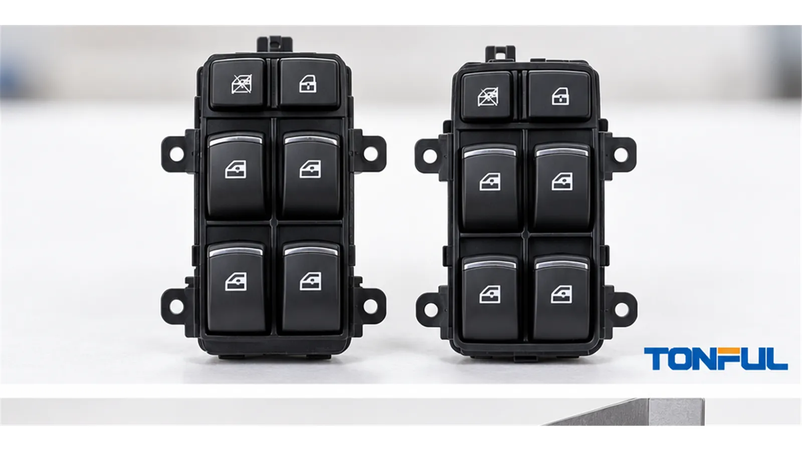
Power window switch fitment should not be determined from appearance, one catalog field, or a supplier statement alone. A candidate can fit the door trim and mate with the connector yet use different populated cavities, terminal functions, resistor values, illumination polarity, one-touch logic, or module communication. These differences can cause missing functions, reversed glass movement, diagnostic faults, or electrical damage.
Use this checklist to compare a removed part with a candidate sample before ordering inventory or approving a catalog application. The process separates vehicle identity, mechanical fit, connector fit, electrical architecture, functions, and completed-vehicle validation. Product drawings, vehicle service information, customer requirements, and approved samples remain the acceptance sources; this guide does not provide a universal pinout or test limit.
On this page: Twelve Fitment Checks | Mechanical and Connector Fit | Electrical Architecture and Pinout Verification | Functions, Vehicle Validation and Release
Twelve Fitment Checks
Quick Decision Framework
| No. | Check | Required evidence | Main release risk |
|---|---|---|---|
| 1 | Vehicle/VIN context | Vehicle record, VIN fields where applicable, source date | Wrong model or option content |
| 2 | Market and production date | Destination market and production/VIN boundary | Mid-year or regional configuration change |
| 3 | Door and steering position | Driver/passenger, front/rear, physical side, LHD/RHD | Wrong master layout or harness |
| 4 | Full OE and supersession chain | Complete label, number type, source, direction, conditions | Invalid or one-way interchange treated as universal |
| 5 | Master/passenger role | System description, button scope, circuit diagram | Wrong control authority or lockout path |
| 6 | Bezel and mounting dimensions | Controlled dimensions, datums, fit sample | Poor seating, retention, clearance, or appearance |
| 7 | Connector shell and keying | Straight connector-end views and mating interface | Forced mating or incomplete latch |
| 8 | Populated cavity map | Numbered cavity drawing for both parts | Same shell but different terminal population |
| 9 | Electrical architecture | Diagram and product-specific test method | Direct-load switch confused with coded or network input |
| 10 | Button-stage/continuity matrix | OFF, UP, DOWN, AUTO, lock and secondary-state results | Missing, inverted, or incorrect commands |
| 11 | One-touch and initialization | System ownership and vehicle service procedure | Manual function passes but automatic operation fails |
| 12 | Installed vehicle validation | Identified vehicle, sample, test record, approver, date | Bench result incorrectly released as vehicle fitment |
An Unknown result is not a pass. Stop release when vehicle scope, connector orientation, pinout, architecture, or safety-related automatic-window behavior remains unresolved.
Mechanical and Connector Fit
Confirm Vehicle, OE Reference, and Door Position
Record make, model, model year, body style, trim, destination market, production date or VIN range, and relevant options. Describe position as driver master, front passenger, rear-left, or rear-right, then record LHD or RHD. “Left” by itself is ambiguous because catalogs may use vehicle-side or viewer-side conventions.
Capture every character of the OE service number and identify its source. Separate OE service, superseded OE, supplier, engineering, housing/casting, and customer stock numbers. A molded number on the plastic housing may identify a shared subcomponent rather than the complete switch. The OE-number verification guide explains how to record supersession direction and validation status.
For U.S.-market vehicles, NHTSA vPIC can support manufacturer-reported vehicle identification data. It does not confirm power window switch interchangeability, OE supersession, connector pinout, electrical architecture, or product acceptance.
Measure Bezel, Mounting, and Installed Clearance
Compare face length and width, bezel contour, housing depth, clip and screw locations, locating tabs, connector clearance, rocker travel, and surrounding trim gap. Use drawing datums or a controlled fixture rather than relying on perspective photographs. Install the sample without trimming the panel, forcing clips, loading the harness, or allowing the rocker to contact adjacent trim.
| Mechanical field | Removed part | Candidate sample | Requirement/source | Result |
|---|---|---|---|---|
| Bezel length/width | Enter result | Enter result | Drawing or approved master | Pass/Fail |
| Housing depth | Enter result | Enter result | Vehicle interface | Pass/Fail |
| Clip/tab position | Enter result | Enter result | Drawing and photo | Pass/Fail |
| Screw/locator position | Enter result | Enter result | Drawing | Pass/Fail |
| Rocker and trim clearance | Enter result | Enter result | Installed sample | Pass/Fail |
| Connector access/harness strain | Enter result | Enter result | Installed sample | Pass/Fail |

Housing depth, mounting tabs, connector orientation, and vehicle-interface dimensions should be recorded against controlled requirements.
Compare Connector Shell and Populated Cavities
Photograph both connector faces straight-on with the latch, keyway, or cavity-one reference visible. Compare shell family, keying ribs, polarization, latch, cavity count, populated terminals, terminal size, seal interface, and signs of bent or backed-out terminals. Never mirror one photo to make it resemble the other.
A physically mating connector is not proof of electrical fit. Record empty cavities as well as populated ones because a missing illumination, lockout, communication, or motor terminal can distinguish configurations within the same shell family.
Electrical Architecture and Pinout Verification
Identify the Control Architecture Before Energizing
Determine whether the switch directly reverses motor polarity, switches a relay, sends a low-current request to a BCM or door module, produces resistance-coded states, or communicates over LIN/CAN or another specified interface. A master switch may combine more than one method. Terminal size and button count cannot establish the architecture.
Direct motor-current contacts require verification of the actual current path, terminal allocation, loaded voltage drop or contact resistance, and thermal behavior under product-specific conditions. Low-current request switches require the correct reference voltage, ground, logic state, or resistance range. Networked units add hardware, software, coding, wake/sleep behavior, diagnostics, and initialization dependencies.
The Master vs Passenger Power Window Switch guide explains how master-series contacts, lockout, door modules, resistance coding, and network commands change the relationship between local and driver controls.
Complete a Pin and Cavity Matrix
Do not use a generic internet pinout. Number cavities from the controlled connector drawing and state the viewing direction. Complete one row for every cavity, including blanks.
| Cavity | Removed-part terminal/function | Candidate terminal/function | OFF state | UP state | DOWN state | AUTO/secondary state | Evidence source | Result |
|---|---|---|---|---|---|---|---|---|
| Enter cavity | Power, ground, motor, illumination, lock, signal, network, or empty | Enter candidate function | Open/closed/value | Path/value | Path/value | Path/value | Diagram and test | Pass/Fail |
| Enter cavity | Enter function | Enter candidate function | Enter | Enter | Enter | Enter | Enter source | Pass/Fail |
| Enter cavity | Enter function | Enter candidate function | Enter | Enter | Enter | Enter | Enter source | Pass/Fail |
For direct reversing switches, record which terminals connect in neutral, UP, and DOWN and which polarity reaches the motor. For resistance-coded switches, record each commanded resistance window, tolerance, test points, instrument method, and module recognition. For relay or BCM requests, record the expected voltage or ground logic and the receiving input. For networked products, record interface, message or state evidence, software revision, coding, and DTC behavior without inventing universal values.
Verify Illumination, Lockout, and Control Authority
Identify power, ground, illumination supply, illumination return, dimming or PWM input, and polarity. A switch can operate the glass while backlighting remains dark or behaves incorrectly. Check symbol orientation, color, brightness method, and light leakage only against the approved appearance requirement.
Trace the window-lock path. In some circuits, the master interrupts local power or contact paths; in others it sends a module request. Confirm whether a passenger command passes through master contacts, shares a module input, or travels independently. If disconnecting or failing the master disables a local switch, document that architecture rather than blaming the passenger sample.
The How to Test a Power Window Switch guide provides a safe diagnostic framework using vehicle-specific diagrams and identified test points.
Functions, Vehicle Validation and Release
Separate One-Touch Input From Anti-Pinch Control
Verify manual UP and DOWN, first and second rocker stages, AUTO indicator or coded output, neutral return, lockout, locks, mirrors, illumination, and any secondary functions. Then identify where automatic-window logic actually resides.
Approval of the switch alone does not establish compliance of the completed power-window system. Identify whether one-touch control, obstacle detection, automatic reversal, current sensing, position learning, and initialization belong to the switch, motor controller, door module, or vehicle system. A bench sample can produce the expected request while the installed system still requires coding or relearn.
After battery disconnection or component replacement, follow the vehicle-specific service procedure for initialization. Record whether relearn completed, learned travel limits are valid, DTCs are absent or resolved, and manual and automatic operation work from every authorized control. Do not improvise an initialization sequence from another vehicle.
Use a Copyable Fitment Record
| Check field | Removed part | Candidate sample | Evidence source | Result |
|---|---|---|---|---|
| Full OE number and type | Enter | Enter | Label/catalog | Verified/Conditional/Fail |
| Vehicle, market, production range | Enter | Enter | Vehicle record | Result |
| Door position and LHD/RHD | Enter | Enter | Vehicle/application record | Result |
| Master/passenger role | Enter | Enter | Circuit description | Result |
| Connector cavities/keying | Enter | Enter | End-view photo/drawing | Result |
| Populated terminals | Enter | Enter | Cavity map | Result |
| Switch architecture | Enter | Enter | Diagram/test | Result |
| Manual UP/DOWN | Enter | Enter | Vehicle test | Result |
| One-touch stages | Enter | Enter | Function test | Result |
| Lockout and secondary functions | Enter | Enter | Function matrix | Result |
| Relearn required/completed | Enter | Enter | Service information | Result |
| Final disposition | Reference | Candidate ID/lot | Approval record | Approved/Conditional/Rejected |
Validate the Installed Vehicle and Control Evidence
Use an identified sample and vehicle. Verify seating, retention, connector latch, harness clearance, every rocker from every permitted control location, lockout, illumination, automatic functions, retained-power behavior where applicable, diagnostics, and post-installation condition. The switch-versus-motor-versus-regulator guide helps prevent a motor, regulator, harness, or module fault from being misclassified as poor switch fitment.

Installed validation should confirm retention, harness clearance, manual and automatic functions, and the exact vehicle application.
Apply Evidence-Control Rules Once
Maintain one evidence index containing vehicle source, document revision, OE chain, sample and lot, photograph orientation, dimensions, cavity map, pinout, architecture, function results, test equipment, conditions, acceptance source, approver, and date. If sources conflict, retain them, mark the decision unresolved, and obtain clarification from the controlling vehicle, customer, engineering, or supplier source. Do not choose the more convenient record.
Sample approval applies only to the named configuration. Control changes to housing, resin, contacts, plating, springs, resistor values, PCB, software, illumination, connector, tooling, site, sub-supplier, test method, packaging, and labels. Use the Power Window Switch RFQ and Sample Approval Checklist to define quotation and release evidence before expanding fitment claims.
Work With TONFUL
TONFUL’s automotive power window switch range presents current vehicle applications and OE reference numbers. Send the exact vehicle and market, production range, door position, LHD/RHD, complete OE reference, removed-part photos, dimensions, connector-end view, cavity map, pinout, architecture, function matrix, sample quantity, and validation requirements. Final fitment remains tied to controlled evidence and an approved application sample.
