
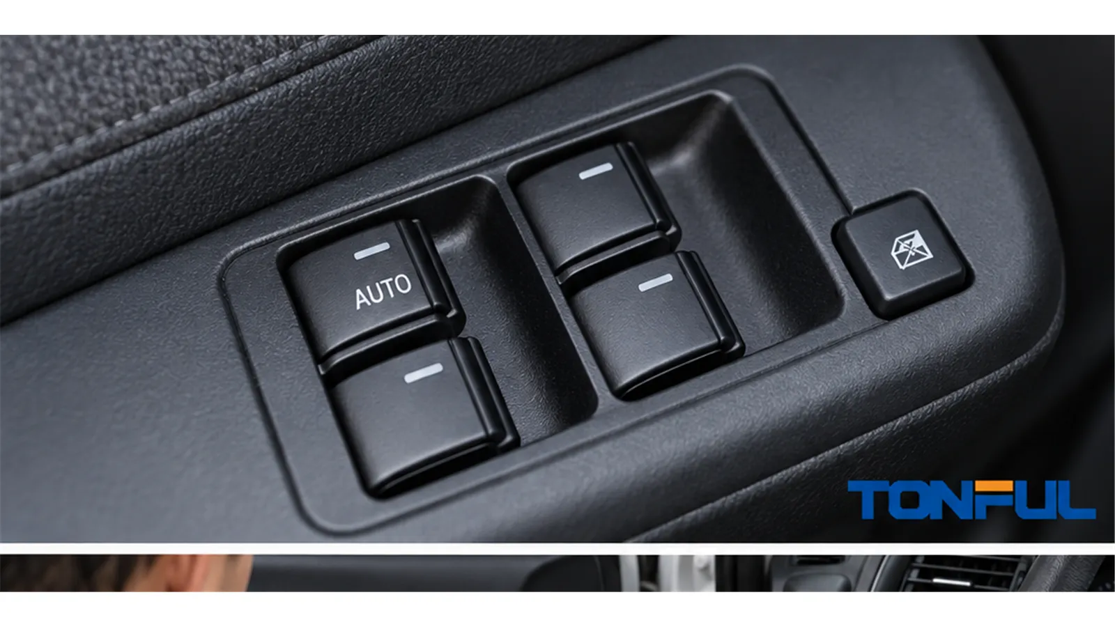
Selecting a one-touch, auto-down or auto-up power window switch should not be based on rocker appearance or connector fit alone. The second detent may be a separate contact, a resistance value, a voltage-coded input, or a digital request. The command may then be interpreted by the master switch, door module, body controller, or motor electronics. A replacement can therefore fit physically and operate manually while its express function remains unavailable or unsafe.
This guide explains how manual, one-touch, auto-down, and auto-up functions differ; where automatic-closing responsibilities may reside; how to investigate common symptoms; and what evidence buyers should request before approving a sample. It does not publish a universal pinout, resistance value, relearn routine, or acceptance limit because those details are application-specific.
On this page: Operating Modes and Signal Types | System Responsibility and Safety Boundary | Diagnosis and Initialization | Replacement Verification and Release
Operating Modes and Signal Types
Manual, One-Touch, Auto-Down, and Auto-Up
In manual mode, glass movement normally continues only while the driver holds the rocker. One-touch or express mode allows travel to continue after release. Auto-down generally involves fewer upper-frame closing hazards than auto-up, but its control logic, stop behavior, and vehicle-specific safety requirements must still be verified. A vehicle may provide auto-down at the driver door only, express operation on every door, or different functions by market, trim, production date, and control-module version.
The tactile interface can also be misleading. A two-stage rocker may provide manual and express requests, but it does not prove which component performs sustained movement. Likewise, an AUTO legend does not prove both directions are automatic. Build a function matrix for every door and direction: manual up, manual down, auto-up, auto-down, lockout, remote operation, retained accessory operation, illumination, and any initialization requirement.

Compare each rocker stage with the vehicle-specific command or circuit response; appearance alone cannot identify express-window architecture.
Common Express-Input Implementations
Several electrical architectures can produce similar user behavior:
| Signal implementation | What the switch may output | How to identify it |
|---|---|---|
| Independent second-detent contact | A separate continuity path for express request | Compare connector cavity functions and continuity at neutral, first detent, and second detent using the correct diagram |
| Resistance-coded input | A different resistance window for each direction or stage | Measure only at specified terminals and compare with the product drawing or vehicle procedure |
| Voltage-coded input | A module interprets defined voltage levels | Check reference voltage, ground, loaded signal voltage, and permitted tolerance under specified conditions |
| Electronic master-switch logic | Internal electronics interpret the rocker and issue a controlled output | Verify power, ground, switch-state data, hardware number, and software or calibration revision |
| LIN/CAN door-module request | A digital message represents the selected function | Use vehicle diagnostics, network diagrams, DTCs, and live data; continuity alone is insufficient |
| Motor-controller express logic | The switch requests movement while the motor electronics manage continued travel | Confirm request input, motor-controller version, feedback devices, learned position, and diagnostic state |
Do not infer the architecture from pin count. A multi-pin connector may include illumination, lockout, door locks, mirror controls, or network lines, while a low-pin-count switch may use resistance coding. The How to Test a Power Window Switch guide explains how to identify circuit boundaries before probing. The Master vs Passenger Power Window Switch guide further distinguishes local requests from master authorization and door-module control.
System Responsibility and Safety Boundary
Map Each Automatic-Closing Responsibility
Auto-up is a system function, not necessarily a switch function. Approval must identify the component that creates the request, decides to continue movement, estimates glass position, detects an obstruction, stops the motor, reverses direction, stores learned values, and communicates faults.
| Function | Possible responsible component | Evidence required |
|---|---|---|
| Second-detent one-touch input | Switch | Contact, resistance, voltage, or network-command matrix for every rocker stage |
| Continued-running decision | Switch electronics, door module, BCM, or motor controller | System architecture, logic description, hardware/software version, and state data |
| Glass position | Motor sensor, motor controller, or door module | Position data, sensor description, learned-limit status, and service information |
| Motor speed or ripple monitoring | Motor electronics or module | Feedback method, signal trace, diagnostic coverage, and approved test plan |
| Current or force evaluation | Motor controller, door module, or system controller | Detection principle, load conditions, calibration source, and verification record |
| Obstacle decision | Motor controller, door module, or vehicle system | Risk analysis, detection logic, environmental conditions, and validation plan |
| Stop and automatic reversal | System controller and motor drive | Vehicle-level test method, acceptance source, results, and failure response |
| Initialization and learned values | Door module, motor controller, or vehicle system | Vehicle-specific service procedure, prerequisites, stored status, and completion evidence |
| Network authorization and diagnostics | Door module, BCM, gateway, or master switch | Network topology, coding, messages, DTCs, and compatible software revision |
Approval of the switch alone does not establish compliance or safe operation of the completed automatic-closing window system. A switch sample can demonstrate its assigned input behavior, fit, connector interface, and documented outputs. It cannot by itself prove obstacle detection, automatic reversal, force control, learned travel limits, or complete vehicle behavior when those functions reside elsewhere.
U.S. Vehicle-Level Requirements
For applicable U.S.-market vehicles, 49 CFR §571.118 addresses vehicle-level operating, actuation, and qualifying automatic-reversal requirements for power-operated window, partition, and roof-panel systems. It is not a stand-alone certification standard for an individual switch and does not establish universal switch pinouts or component acceptance values.
The official NHTSA FMVSS 118 laboratory test procedure is organized around compliance testing of the completed system. Buyers should use the applicable regulatory version, vehicle requirements, customer specification, and approved validation plan. Passing a bench test on a switch does not demonstrate completed-vehicle compliance.
The Power Window Anti-Pinch Systems guide explains how obstacle detection, motor feedback, learned position, and reversal logic interact beyond the switch input.
Diagnosis and Initialization
Use Symptoms to Select the Next Test
Do not replace the switch before separating a missing request from lost initialization, mechanical drag, motor feedback, module configuration, power supply, and network faults.
| Symptom | More likely direction | Checks to prioritize |
|---|---|---|
| Manual works but automatic mode fails | Lost initialization, missing second-detent input, or module state | Detent feel, switch-state data, command matrix, DTCs, and learned-limit status |
| Auto-down works but auto-up fails | Configuration, anti-pinch state, position learning, or auto-up channel | Auto-up authorization, second-stage output, reversal status, motor feedback, and coding |
| One-touch fails after battery disconnection | Learned travel limits or module state lost | Vehicle-specific initialization procedure, prerequisites, supply stability, and completion confirmation |
| Glass reaches the top then reverses | Mechanical resistance or false obstruction detection | Run-channel condition, regulator alignment, glass adjustment, current/speed feedback, and pinch status |
| Master provides express movement but local switch does not | Permission logic, local switch stage, or passenger-door input | Lockout state, master/passenger function matrix, local request, wiring, and module data |
| Replacement produces DTCs | Wrong architecture, coding, hardware, or software | Complete OE chain, connector population, network communication, coding, and module revision |
| Express operation is intermittent | Worn detent/contact, terminal issue, voltage instability, or network fault | Repeatable rocker-stage capture, terminal fit, loaded voltage, event data, and harness movement |
| Direction is reversed after replacement | Incorrect pinout, motor polarity path, or application version | Connector end view, cavity map, circuit diagram, removed sample, and approved function test |
Mechanical evidence matters. Increased guide-channel friction, a distorted regulator, glass misalignment, or voltage loss can increase motor load and trigger a protective response even when the switch command is correct. Record glass position and operating condition when the symptom occurs rather than describing only “auto not working.”
Initialization Is Application-Specific
Initialization may teach upper and lower travel limits, identify motor direction, establish position references, clear a protection state, or synchronize a replacement module. The sequence may depend on door position, ignition state, glass starting position, switch-hold duration, diagnostic-tool access, DTC status, and uninterrupted voltage. A generic “hold for five seconds” instruction must not be published unless supported by the exact vehicle service procedure.
Before initialization, resolve binding, regulator, power, ground, connector, and module faults. During the procedure, record vehicle identity, OE and software references, battery condition, starting glass position, operator steps, confirmation signals, DTCs, and final manual/express results. Afterward, verify every authorized control location and direction. Where automatic closing is present, complete the vehicle-specific safety and reversal checks required by the applicable procedure.

Record the starting position, service procedure, learned status, final travel, and system-level checks during initialization.
Replacement Verification and Release
Evidence-Control Rules
Use one controlled evidence register rather than repeating generic cautions in every test section. For each source, record its identifier, issuer, revision, date, market, application boundary, and reviewer. Identify every sample by part number, revision, lot, build status, and photographs with a consistent connector-end orientation. If the removed part, catalog, drawing, service information, and test result conflict, place the decision on hold and obtain engineering, customer, or vehicle-manufacturer clarification. Never resolve a conflict by choosing the easiest source.
Unknown data must remain Unknown. A prototype can support interface review but does not prove production consistency. Design qualification, process validation, end-of-line testing, incoming inspection, installed-vehicle validation, and field-return evidence answer different questions and should remain separately identified.
Replacement and Sample-Approval Checklist
Use the Power Window Switch Fitment Checklist to control mechanical and electrical comparison. At minimum, verify:
- vehicle, market, production range, trim, door position, and LHD/RHD;
- complete OE service number and supersession direction;
- bezel, mounting, housing depth, connector keying, latch, and clearance;
- populated cavity map, power, ground, illumination, signal, motor, and network terminals;
- direct-reversing, resistance-coded, voltage-coded, electronic, or network architecture;
- neutral, manual-up/down, and every express-stage output;
- master authorization, lockout, passenger control, and illumination behavior;
- hardware, software, calibration, coding, and initialization requirements;
- manual travel, express travel, DTC state, and installed-vehicle results;
- approved sample identity, test records, packaging, traceability, and change control.
The OEM vs Aftermarket Power Window Switch comparison explains why labels and price cannot replace validation evidence. TONFUL’s automotive power window switch range presents current vehicle applications and OE references; confirm the exact vehicle, OE reference, connector, pinout, functions, approved sample, and project-specific validation plan before ordering.
Release Decision
Classify the result as Rejected, Conditional, Sample Approved, or Production Approved. Rejected means a mandatory interface, function, or evidence requirement failed. Conditional approval must identify the deviation, affected application and quantity, owner, expiry, risk control, and closure evidence. Sample approval applies only to named samples under recorded conditions; it is not automatic mass-production approval. Production approval requires production-intent evidence and remains limited to the approved product, factory, process, revision, and application.
Work With TONFUL
For a one-touch power window switch inquiry, send TONFUL the vehicle and market, complete OE reference, door position, removed-part and connector-end photographs, cavity map, circuit or network architecture, manual and express function matrix, software or initialization requirements, annual demand, packaging, and validation plan. This information allows the switch interface and project scope to be reviewed without implying that switch approval alone validates the complete automatic-closing system.
