
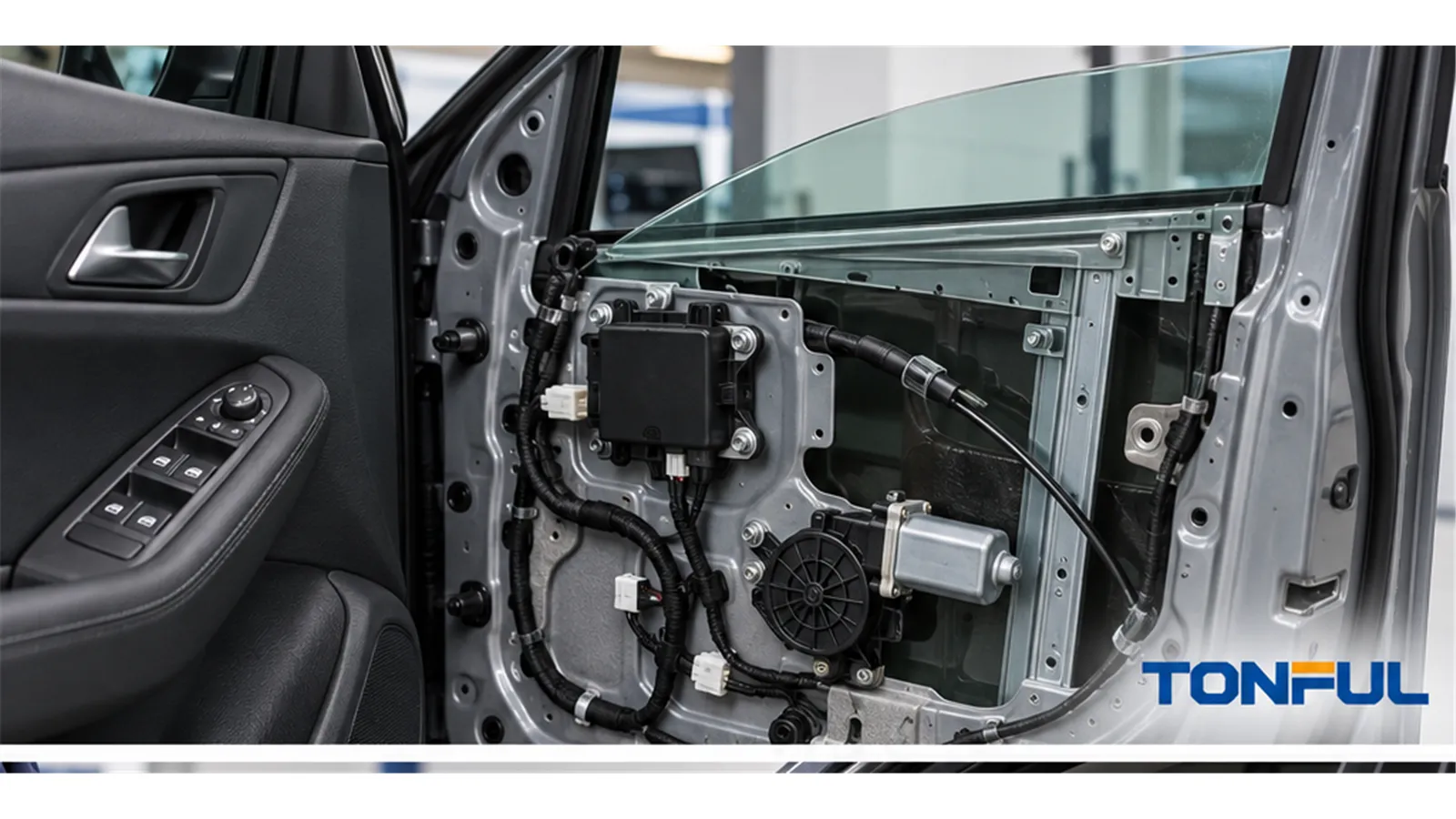
A power window anti-pinch system cannot be evaluated from the switch label, connector shape, or one successful auto-up cycle. Automatic closing depends on a chain that may include the rocker input, door electronics, motor controller, position or speed feedback, current monitoring, learned travel limits, mechanical window condition, and reversal logic. A fault anywhere in that chain can disable express-up operation or cause false reversal.
The practical task is to identify where each safety-related function resides, what evidence proves the switch interface, how the completed system is validated, and what must be repeated after replacement or power loss. This article does not provide universal force limits, current thresholds, pinouts, or initialization steps; use applicable regulations, vehicle requirements, controlled drawings, service information, or an approved test plan.
On this page: How Anti-Pinch Protection Works | System Responsibility and Regulatory Boundary | Diagnosis, Initialization and Safe Testing | Replacement and Production Release
How Anti-Pinch Protection Works
From Express-Up Request to Automatic Reversal
The process normally starts when the driver pulls the switch into an express or second-detent position. Depending on the architecture, the switch may close a dedicated contact, produce a resistance or voltage code, or transmit a digital command. A controller authorizes continued motor operation after the rocker is released and monitors information related to glass travel and motor load.
If the controller identifies an obstruction within its defined detection zone and operating conditions, it commands the motor to stop and reverse according to the approved system logic. That behavior cannot be attributed automatically to the switch. In many designs, the switch only requests movement while the motor electronics or door module performs detection, decision, and reversal.

Anti-pinch verification must use the specified procedure and test fixture; hands and improvised objects must never be placed in the glass path.
Common Obstruction-Detection Methods
The sensing strategy changes what must be tested and which replacement components require initialization or coding.
| Detection method | Information used by the controller | Evidence to verify | Typical diagnostic concern |
|---|---|---|---|
| Motor-current monitoring | Increase or pattern change in motor current | Current waveform, operating voltage, mechanical load, software/calibration and test conditions | Channel friction or voltage variation may resemble an obstruction |
| Motor-speed or ripple analysis | Motor rotation speed or commutation ripple | Sensor or ripple signal, sampling logic, learned baseline and motor version | Worn motor, electrical noise or mechanical drag can distort feedback |
| Position-based estimation | Glass position and expected travel behavior | Position signal, upper/lower learned limits, travel map and initialization status | Lost learning or wrong regulator geometry can cause false reversal |
| Hall-effect or encoded motor feedback | Pulses or position data from the motor assembly | Sensor output, pulse count, direction, controller compatibility and DTCs | Wrong motor/controller revision may provide incompatible feedback |
| Proximity sensing | Detection before physical contact in supported systems | Sensor type, detection zone, environmental range and vehicle-level validation | Dirt, alignment, light conditions or wrong calibration may affect detection |
| Combined model | Current, speed, position and environmental compensation | Architecture description, calibration version, validation matrix and fault handling | One apparently normal signal does not prove the complete decision model |
No single generic threshold should be copied between vehicles. Window mass, seals, regulator geometry, temperature, supply voltage, motor characteristics and software strategy all influence the measured signals. A current spike is evidence to investigate, not automatically proof of a trapped object.
Mechanical Condition Is Part of the System
Anti-pinch logic operates on a physical window mechanism. Tight run channels, glass misalignment, bent regulator components, deteriorated seals, contamination or low voltage can increase load and create false reversals. Conversely, a mechanical or electrical change may alter expected feedback without producing an obvious visible defect.
Record the glass starting position, direction, ambient condition, door state, supply voltage and exact point of reversal. Compare left and right doors only when their hardware, calibration and function scope are equivalent. Lubrication or adjustment should follow approved service information; an improvised change can mask evidence or affect materials.
System Responsibility and Regulatory Boundary
Define Who Performs Each Function
The switch should be approved only for its assigned role. Use a responsibility matrix before testing or sourcing:
| Function | Possible responsible component | Required evidence |
|---|---|---|
| Express-up or second-detent request | Power window switch | Contact, resistance, voltage or network-command matrix for every rocker stage |
| Continued-running authorization | Master switch electronics, door module, BCM or motor controller | System architecture, state data, software version and authorization conditions |
| Glass position or travel estimate | Motor sensor, motor controller or door module | Position data, learned endpoints, sensor description and diagnostic status |
| Motor current, speed or ripple monitoring | Motor electronics or controller | Signal traces, measurement conditions, calibration source and fault coverage |
| Obstacle classification | Motor controller, door module or system software | Detection principle, decision logic, environmental range and validation plan |
| Stop and reversal command | System controller and motor drive | Vehicle-level response test, acceptance source, result and failure reaction |
| Initialization and relearn | Door module, motor controller or vehicle system | Vehicle-specific procedure, prerequisites, learned state and completion record |
| Diagnostics and network authorization | Door module, BCM, gateway or master assembly | DTCs, communication data, coding and compatible hardware/software revisions |
Approval of the switch alone does not establish compliance or safe operation of the completed automatic-closing window system. A switch test may demonstrate correct fit, detents, electrical output and communication request. It cannot independently validate obstacle detection, force evaluation, reversal distance, learned limits or whole-vehicle behavior when those functions reside elsewhere.
The One-Touch, Auto-Up and Auto-Down Power Window Switch guide explains common express-input architectures. The Master vs Passenger Power Window Switch guide helps identify whether a local request passes through a master assembly or door module.
FMVSS 118 Is a Vehicle-Level Requirement
For applicable U.S.-market vehicles, 49 CFR §571.118 addresses operating, actuation and qualifying automatic-reversal requirements for power-operated window, partition and roof-panel systems. It is not a supplier-audit criterion, vehicle-data source, universal switch test method or stand-alone certification standard for an individual replacement switch.
The official NHTSA FMVSS 118 laboratory test procedure is intended to obtain compliance-test data using the completed vehicle system and controlled equipment, conditions and records. It also states that the laboratory procedure does not replace the standard itself or guarantee compliance when used alone. Confirm the applicable regulatory version and market requirements with qualified personnel.
Diagnosis, Initialization and Safe Testing
Failure-to-Evidence Matrix
Use the symptom to choose the next measurement instead of condemning the visible switch.
| Symptom | More likely investigation path | Evidence to collect |
|---|---|---|
| Manual movement works but auto-up is unavailable | Express input, learned limits, authorization or module status | Second-detent state, switch command, DTCs, initialization status and live data |
| Window reaches the top and reverses | Excess mechanical load or false obstacle detection | Run-channel condition, glass alignment, regulator load, motor feedback and reversal position |
| Auto-down works but auto-up does not | Auto-up configuration, anti-pinch state or direction-specific input | Function matrix, coding, second-stage output, learned upper limit and controller data |
| Function fails after battery disconnection | Lost position learning or protection state | Vehicle-specific relearn procedure, supply condition, DTCs and learned-value status |
| Reversal is intermittent | Borderline friction, terminal voltage loss, sensor variation or unstable learning | Loaded voltage, repeatable travel data, temperature, harness condition and feedback trace |
| New switch creates a DTC or no express request | Wrong architecture, pinout, hardware or communication revision | OE chain, cavity map, network messages, software number and removed-part comparison |
| One door behaves differently from the others | Door-specific hardware, calibration, local module or mechanical condition | Door function matrix, module identity, local switch data, motor/regulator and coding |
| Remote closing differs from interior operation | Authorization conditions or vehicle configuration | Key/ignition state, remote command source, locking state, market configuration and module data |
The How to Test a Power Window Switch article provides a diagram-based approach for switch inputs and outputs. Use it to evaluate the switch portion of the chain, not as a substitute for system-level anti-pinch testing.
Initialization and Learned Limits
Some systems learn upper and lower positions, motor characteristics or reference values used during automatic movement. Battery disconnection, regulator adjustment, motor replacement, module replacement, switch replacement or a detected fault may require a defined initialization process. Requirements differ by vehicle; a generic button-hold sequence can be ineffective or unsafe.
Before relearning, inspect the glass, channels, seals, regulator, connector, supply and grounds. Follow the current vehicle-specific procedure, including prerequisites such as ignition state, door position, DTC handling, starting glass position and stable voltage. Record the procedure identifier, vehicle, component versions, operator steps, confirmation signals, learned status and final manual/express results. Do not repeatedly initialize a system to conceal unresolved mechanical drag.
Safe Verification and Test Records
Never use fingers, hands or an improvised hard object to test automatic reversal. Use only the specified test equipment or compliant fixture under the applicable vehicle, customer or regulatory procedure. Isolate the area, keep personnel clear of moving glass and stop testing if the architecture, procedure, equipment or safety controls are uncertain.

A usable anti-pinch test record connects the vehicle, system configuration, calibrated equipment, controlled obstruction fixture and measured response.
| Record field | Required entry |
|---|---|
| Vehicle and system identity | Vehicle, market, production range, door, OE references and hardware/software revisions |
| Test purpose | Diagnosis, development validation, qualification, compliance, service verification or production audit |
| Preconditions | Glass/regulator condition, learned state, DTC state, voltage, temperature and door/ignition status |
| Equipment and fixture | Model, range, resolution, accuracy, calibration status, fixture identity and placement |
| Procedure | Controlled document, revision, sequence, repetitions and invalid-test rules |
| Raw results | Starting position, detection point, force or signal where applicable, stop/reversal response and final position |
| Failure evidence | Symptom, DTCs, traces, photographs, preserved parts and environmental conditions |
| Decision | Acceptance source, pass/fail, deviation, reviewer and date |
Do not combine design validation, regulatory compliance testing, end-of-line testing and service diagnosis into one unsupported “anti-pinch tested” claim. Each has a different sample population, purpose and acceptance source.
Replacement and Production Release
Verify the Replacement Scope
A replacement decision should confirm the exact vehicle, market, production range, door position and LHD/RHD; complete OE number and supersession direction; housing and mounting; connector keying and populated cavities; switch architecture; every manual and express stage; illumination and lockout; module communication; and coding or initialization requirements. The Power Window Switch Fitment Checklist provides a structured comparison, while the OEM vs Aftermarket Power Window Switch guide explains why branding and connector appearance do not replace evidence.
Installed validation must verify manual movement, express operation, DTC status, authorization from each control location and every vehicle-specific post-replacement safety check. If anti-pinch logic resides in the motor or module, changing the switch may still require confirmation that commands and learned states remain correct. If architecture evidence conflicts, do not release compatibility.
Supplier and Production Evidence
For a switch that includes electronics or anti-pinch-related decision logic, request controlled hardware, software and calibration revisions in addition to mechanical and electrical drawings. Review PCB assembly, ESD controls, programming records, software-version verification, end-of-line coverage, traceability and change notification where applicable. For a passive request switch, focus on detent stages, contact or encoded outputs, terminal retention, connector position, durability evidence and production test coverage.
The release package should identify approved samples, manufacturing site, tooling status, critical sub-suppliers, test fixtures, packaging and label controls. Changes to contacts, resistance networks, electronics, firmware, motor compatibility, materials, tooling, process, site or test method require risk review and approval when specified. Sample approval does not automatically authorize mass production.
Final Release Checklist
- The switch role and complete system architecture are documented.
- Express request, sensing, decision, stop, reversal and initialization responsibilities are assigned.
- Mechanical drag, supply voltage and feedback faults have been separated from switch faults.
- Vehicle, OE chain, connector, pinout, hardware, software and function matrix agree.
- Testing uses an approved procedure, safe fixture, calibrated equipment and defined acceptance source.
- Raw results, invalid tests, deviations, DTCs and failure evidence are retained.
- Installed-vehicle initialization and specified safety checks are complete.
- Approved scope, traceability, packaging and change-control requirements are recorded.
Work With TONFUL
TONFUL’s automotive power window switch range presents current vehicle applications and OE references. For project review, provide the vehicle and market, OE reference, door position, removed-part and connector photographs, pinout or command matrix, system architecture, manual and express functions, initialization requirements, annual demand, packaging and validation plan. TONFUL can review the applicable switch interface and sample scope; final anti-pinch compliance and safe operation remain vehicle-system decisions supported by controlled evidence.
