
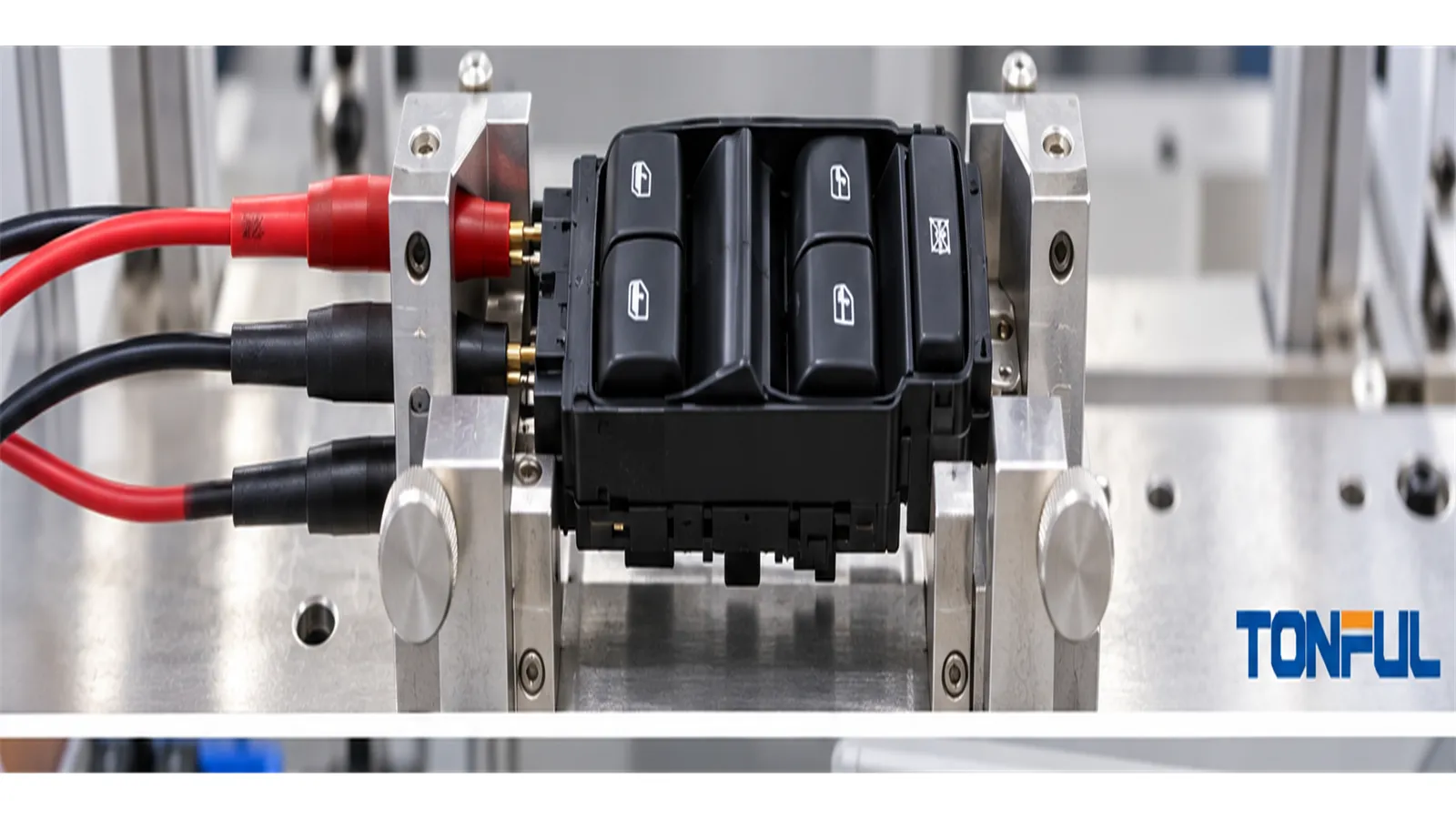
Power window switch contact resistance cannot be judged with a continuity beeper or one unexplained milliohm value. A valid result must identify the exact current path, switch state, Force and Sense locations, test current, polarity, instrument, fixture, temperature and acceptance source. Moving either Sense point changes what resistance is included, so results from different fixtures may not be comparable even when they use the same meter.
Method depends on architecture. Direct polarity-reversing contacts require low-resistance and loaded-drop evidence; coded or networked switches require state-window or communication tests. This guide does not invent universal limits, currents or pinouts.
On this page: Define the Circuit and Method | Build a Four-Wire Kelvin Setup | Interpret Results and Diagnose Failures | Control Records and Release
Define the Circuit and Method
Identify What the Number Represents
Before connecting an instrument, mark the connector end view, cavity numbers, switch direction and rocker stage. Then define the electrical boundaries:
| Measured path | What may be included | Main use |
|---|---|---|
| Internal contact path | Selected internal contacts and conductors between component terminals | Design and production comparison when terminal boundaries are controlled |
| Mated connector plus switch | Harness terminal interfaces, switch terminals and internal contact path | Vehicle-interface or assembly evaluation |
| Harness-to-load path | Wire, splices, connectors, switch and downstream load connection | Vehicle diagnosis and loaded voltage-drop investigation |
| Resistance-coded output | Fixed/variable resistor network and wiper/contact interfaces | Verify each button-state resistance window |
| Electronic or network input | Supply, ground, signal conditioning or communication circuit | Requires voltage, current, state or message testing rather than a simple contact value |
Do not call a complete path “contact resistance” if it includes wire, connector and fixture interfaces without saying so. Conversely, subtracting a wire baseline is valid only when the approved method requires it and the reference length, construction, temperature and connections match.
The Power Window Switch Fitment Checklist helps establish connector orientation, cavity population and architecture before testing. For vehicle diagnosis, the How to Test a Power Window Switch guide explains why a vehicle diagram must define each test point.
Choose Low-Level Resistance or Loaded Voltage Drop
Low-level four-wire measurement is useful for resolving small resistance changes under controlled current. Loaded voltage drop evaluates the path under a specified operating load and can reveal heating, unstable interfaces or load-dependent behavior. Neither method replaces the other automatically.
| Method | Required definition | Key limitation |
|---|---|---|
| Four-wire low resistance | Force/Sense points, current, range, aperture, polarity, stabilization, temperature and offset method | May not reproduce motor-current arcing, heating or contact-force behavior |
| Loaded voltage drop | Load type, current waveform, supply, state, test points, duration and temperature | Includes every resistance between voltage probes and may vary with motor condition |
| Two-wire resistance | Lead/fixture null method and expected uncertainty | Lead and probe resistance can dominate a milliohm-level DUT |
| State resistance | Terminal pair, rocker state, current/voltage and tolerance source | Intended for coded signals, not necessarily a motor-current contact |
A continuity test can identify an obvious open circuit but cannot characterize low resistance accurately. Likewise, a low unloaded result does not prove acceptable voltage drop, temperature rise or durability under the actual load.
Build a Four-Wire Kelvin Setup
Place Force and Sense Connections Deliberately
In a Kelvin setup, one lead pair forces current through the device while a second pair measures voltage. Because Sense current is very small, voltage drop in the Sense leads is minimized. However, every resistance between the two Sense points remains part of the reported result. That can include terminal material, a mated interface, internal conductors, contacts, solder joints or fixture elements located inside the boundary.
The Tektronix low-resistance measurement guide explains why four-wire connection is preferred for low resistance and why Sense connections should be close to the resistance under test. The Keysight resistance-measurement application note covers four-wire connection, offset voltages, thermal EMFs and self-heating considerations.

Force current and Sense voltage connections must be documented independently; the reported result includes the complete path between the Sense points.
Control the Fixture and Instrument
Use mating terminals, connector fixtures or probes appropriate to the approved method. Record contact force, insertion depth, orientation, cleanliness and mating-cycle status. A sharp probe on a plated surface may create a different interface from the vehicle connector. Cable movement, oxidized fixture contacts and inconsistent clamping can create apparent DUT variation.
The equipment record should include instrument model, measurement range, resolution, accuracy, calibration status, aperture/integration time, filtering, current source and compliance settings. Verify the fixture with a controlled short or reference artifact, but do not subtract a fixture value blindly when part of that fixture lies between the Sense points by design. Use repeatability studies to separate measurement variation from product variation.
Reduce Thermal EMF, Offset and Self-Heating Error
When resistance is small, thermoelectric voltages from dissimilar metals and temperature gradients can be significant compared with the measured voltage. Depending on the instrument and approved method, use current reversal, delta measurement or offset-compensated ohms. Record raw positive/negative or current-on/current-off readings rather than reporting only the corrected value.
For stable offset and equal-magnitude reversed current: V+ = VEMF + IR, V- = VEMF – IR, and R = (V+ – V-) / (2I). This cancellation depends on controlled polarity, settling and timing, with no material offset drift during the pair. Tektronix’s current-reversal and delta-method explanation distinguishes current reversal, offset-compensated ohms and three-reading delta measurements.
Allow connections to stabilize after handling. Avoid airflow or local heating that changes junction temperature during a sequence. Select test current high enough for useful signal-to-noise ratio but low enough to avoid changing contact condition or causing unwanted self-heating, unless the method intentionally evaluates loaded behavior. The current value and dwell must come from the controlling specification or validated measurement plan.
If resistance changes with current, investigate self-heating, film breakdown or non-ohmic behavior; do not average unlike conditions. Multiple-current testing must be authorized because higher current may alter the interface.
Use a Complete Setup Matrix
| Setup field | Required entry |
|---|---|
| Sample | Part number, revision, lot, cavity/line and sample ID |
| Switch state | Neutral, UP, DOWN, manual/express stage and channel |
| Circuit path | Exact upstream/downstream boundaries and included interfaces |
| Force points | Current-source HI/LO locations and connection method |
| Sense points | Voltage HI/LO locations and orientation |
| Instrument | Model, range, resolution, accuracy, calibration and settings |
| Test condition | Current/load, polarity sequence, dwell and ambient/component temperature |
| Offset control | Reversal, delta, current-off or instrument compensation method |
| Reference | Fixture check, wire baseline or reference artifact when specified |
| Acceptance | Drawing/specification clause, initial limit, aged limit and change limit |
The uncertainty budget should address source-current accuracy, voltage accuracy/noise, thermal-EMF residual, repeatability, fixture stability, Sense-point placement and temperature. Instrument resolution alone is not measurement uncertainty. Measurement capability must be suitable relative to the acceptance band.
Interpret Results and Diagnose Failures
Relate Voltage Drop and Resistance
For a defined path under stable conditions, equivalent resistance is calculated from Ohm’s law:
R = V / I
Illustrative example, not an acceptance limit: if the measured drop is 0.12 V at 8 A, the equivalent path resistance is 0.12 / 8 = 0.015 ohm, or 15 milliohms. This value represents everything between the voltage probes. It should not be labeled internal switch-contact resistance if harness, connector or terminal interfaces are also included.
Motor current may change with glass position, mechanical load and supply voltage. Capture voltage and current at the same time and define the analysis interval. Comparing drop values at different currents or transient points can create a false conclusion. For heating investigations, record duration, ambient and temperatures at the switch, terminals and connector as required.
Compare Initial, Interim and Aged Results
Report each sample rather than only an average. Pair initial and aged measurements on the same path and calculate the change when the specification requires it. Record endurance cycles, electrical load, environmental exposure, mating operations and any cleaning or handling between measurements.
| Result pattern | Evidence to collect | Investigation direction |
|---|---|---|
| High value from first measurement | Repeatability, Sense boundary, terminal fit and sample traceability | Wrong path, fixture interface, contamination, assembly or contact force |
| Increasing value during cycling | Per-sample trend, load waveform, temperature and cycle point | Contact wear, plating loss, debris, spring relaxation or terminal heating |
| Unstable spikes | Time trace, actuator position, harness movement and switch state | Bounce, intermittent contact, loose terminal, solder crack or fixture motion |
| Direction-dependent difference | UP/DOWN path map, contacts, load direction and temperature | Separate contact sets, asymmetrical wear or wiring boundary |
| Value changes after remating | Mating count, insertion marks, retention and connector condition | Interface film, fretting, terminal force or probe disturbance |
| Normal low-level value but high loaded drop | Current waveform, self-heating, contact voltage and connector temperature | Load-dependent interface, insufficient force, arcing or terminal capacity |
| Group average passes with one outlier | Individual raw data, sample history and measurement uncertainty | Local defect or emerging failure hidden by averaging |
Do not clean, remate or disassemble a suspect sample before recording its as-found behavior unless the procedure instructs it. Preserve terminals, contacts, springs, lubricant, PCB/solder joints and contamination for root-cause analysis. The Power Window Switch Endurance Testing guide explains how to link resistance trends to failed-cycle and teardown evidence.
Understand the IEC Method Boundary
IEC 60512-2-2:2003 defines a specified-test-current method for resistance across a pair of mated connector contacts or a contact with a measuring gauge. It can inform a connector-interface method when contractually applicable, but it is not automatically a complete power window switch assembly specification. Do not transfer its scope or any connector acceptance requirement to an internal switch path without a controlled authority.
Control Records and Release
Use a Vertical Test Record

Compare initial and aged samples with the same path, fixture, temperature controls and acceptance-source document.
| Record field | Required entry |
|---|---|
| Sample identity | Part number, revision, lot, build status and sample ID |
| Circuit path | Exact terminals, switch state, included interfaces and diagram reference |
| Instrument | Model, range, resolution, accuracy, calibration and settings |
| Kelvin setup | Force and Sense locations, fixture ID and connection method |
| Test condition | Current/load, polarity, dwell, ambient and component temperature |
| Raw results | Voltage readings, current readings and uncompensated values |
| Corrected result | Compensation method, calculated resistance and uncertainty where required |
| Aging comparison | Initial, interim, aged value, change and exposure history |
| Decision | Acceptance-source document, limit, pass/fail, reviewer and date |
| Exception | Invalid test, interruption, retest authorization and preserved original data |
Define sample quantity, selection, conditioning, retest and invalid-test rules before execution. A fixture slip or instrument overload may invalidate a reading, but the event must remain in the record. A retest does not erase the original result. Measurement-system analysis should match the characteristic and decision risk; a visually stable display alone is not evidence of adequate repeatability.
Connect Measurement to Production Control
For production, define tested paths, stage, coverage and fixture/software revision. End-of-line continuity may detect opens but cannot automatically replace low-resistance or loaded-drop testing. Control verification intervals, reference artifacts, fixture wear, reaction plans and lot traceability.
Relevant product, material, process, supplier, fixture or method changes require risk review and a documented decision on repeated correlation or validation. The Power Window Switch Manufacturer Audit Checklist connects laboratory evidence to process controls.
Final Release Checklist
- Architecture and exact measured path are identified.
- Force and Sense points are shown on a controlled fixture diagram.
- Instrument, current, polarity, offset method, dwell and temperature are recorded.
- Low-level and loaded tests are used only for their approved purposes.
- Initial, interim and aged values remain linked to individual samples.
- Raw, corrected and excluded results are retained with reasons.
- Acceptance limits cite product/customer documents rather than this article.
- Production fixtures, coverage, reaction plans and changes are controlled.
Work With TONFUL
TONFUL’s automotive power window switch range presents current vehicle applications and OE references. For a contact-resistance or voltage-drop project, provide the application, circuit diagram, switch state, Force/Sense boundaries, current or load profile, instrument requirements, temperature, sample plan, initial/aged criteria and report format. TONFUL can review the applicable product and sample scope; final acceptance remains tied to controlled customer or project documentation.
