
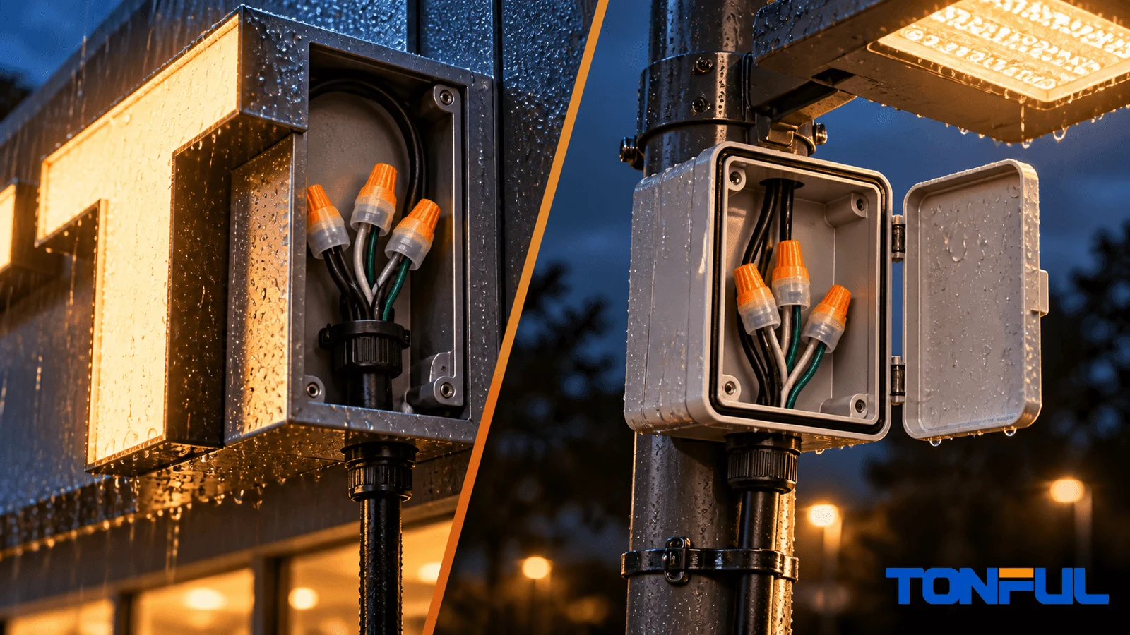
Outdoor signs and luminaires expose electrical connections to condensation, wind-driven rain, temperature changes, UV, and service movement. A sealant-filled wire nut can protect a splice, but selection must follow the equipment’s dry, damp, or wet-location marking, the connector’s approved conditions, the conductor combination, voltage, temperature, and enclosure instructions.
“Outdoor,” “weatherproof,” and “waterproof” are not enough by themselves. The complete installation determines suitability.
Application and Location Requirements
Signs and Luminaires Are Different Product Systems
UL Solutions identifies UL 48 for electric signs, while the official UL 1598 standard page covers luminaires. Line-voltage outdoor luminaires are evaluated as complete products, not merely by the connector inside them. The finished sign or luminaire carries location markings and installation instructions that affect field wiring.
An outdoor sign may contain channel letters, LED modules, Class 2 wiring, power supplies, raceways, and field splice enclosures. A luminaire may contain branch-circuit conductors, drivers, lamp holders, thermal insulation, gaskets, and mounting seals. Use the instructions for the actual equipment rather than a generic outdoor-wiring rule.
Location Markings Come First

| Marking | General environment | Connector question |
|---|---|---|
| Dry location | Normally not exposed to dampness | Is a sealed connector required by the equipment instructions? |
| Damp location | Condensation or protected moisture exposure | Is the connector approved for damp use inside the specified enclosure? |
| Wet location | Water may drip, splash, or flow on equipment | Is the connector and enclosure combination approved for wet use? |
| Below grade or buried | Soil and prolonged moisture exposure | Does the exact splice system have direct-burial approval? |
UL notes that signs can be certified for dry, damp, or wet-location installation. A connector cannot upgrade equipment marked only for a dry location. Likewise, placing a standard connector inside a box does not automatically make the splice suitable for a wet location.
TONFUL’s guide to waterproof connector standards helps separate equipment markings, connector standards, and IP terminology.
Define the Circuit and Safety Boundary
Field work on branch-circuit or line-voltage sign and luminaire wiring should be performed by a qualified person in accordance with the equipment instructions, applicable electrical code, and authority having jurisdiction. This guide is not a substitute for the equipment wiring diagram, required disconnecting procedure, certification construction, permit, or inspection.
De-energize the correct source, verify the absence of voltage with suitable equipment, and identify supply, load, control, dimming, and grounding conductors before opening a splice. Class 2 output wiring does not make adjacent mains input safe. Stop when the voltage class, disconnecting means, conductor function, or enclosure approval cannot be confirmed.
Connector Standards Must Match the Product Structure
UL 486D may apply to a sealed connector system assembled from specified components, while its scope excludes twist-on-style sealed splicing connectors. UL 486G covers sealed twist-on connecting devices. Verify the exact model, certification category, wire combination, installation condition, and current certification record. A reference to UL 486D in a burial guide does not establish that every filled wire nut belongs to that category.
Connector Selection and Installation
Connector Selection Factors
Complete conductor combination
Record every conductor, not only AWG and quantity. Identify copper, aluminum, or another conductor material; solid, stranded, or fine-stranded construction; building wire, fixture lead, or equipment wire; insulation type and diameter; and whether multiple conductors are permitted. A fine-stranded luminaire lead combined with a solid branch conductor may behave differently from two building wires of the same nominal gauge.
Confirm whether the equipment grounding conductor is part of an approved connector combination and whether it must remain separate from current-carrying or control conductors. Do not assume a connector accepts mixed materials, fine strands, several branch wires, or grounding conductors because they physically fit. Use the exact combination table and equipment wiring diagram.
Voltage condition
Some connector datasheets publish a building-wire rating and a separate condition for signs or luminaires. Use the exact wording and application in the current document. Do not copy a rating from another brand or model.
Temperature
Drivers, lamps, sunlight, and enclosed housings can raise local temperature. Compare the connector rating with the equipment’s marked conductors and thermal environment. A sealant temperature does not automatically equal the complete connector rating.
Enclosure space
The connector should fit without sharp wire bends, compression against a cover, or strain on the splice. Consider service access and inspection.
Wet-location and burial scope
Outdoor equipment above grade differs from an underground landscape-lighting splice. If wiring will be buried, use an approved direct-bury system. TONFUL’s direct-burial connector guide can help define application questions, but the product structure and certification category must still be verified against UL 486D, UL 486G, or another applicable requirement.
TONFUL Model Selection Process

TONFUL publishes multiple waterproof wire nut models across different wire ranges and connector sizes. A preliminary choice should be based on:
- Finished equipment type and location marking
- Connector standard or customer specification
- Exact conductor combination
- Voltage and temperature
- Enclosure and wire-routing space
- Installation method
- Target market and required certification
Use TONFUL’s waterproof wire nut selection guide to prepare the application data. Then request the current model drawing, combination table, installation instructions, and certification evidence.
Installation Controls
De-energize and identify conductors
Follow the sign or luminaire instructions and applicable electrical requirements. Confirm conductor function, voltage class, and power isolation before work.
Strip accurately
Use the connector’s specified strip length. Avoid nicking conductors or leaving bare copper outside the shell.
Follow pre-twist instructions
Some products allow aligned conductors; others require a defined preparation. Do not transfer instructions from a different connector.
Tighten and inspect
Install the connector fully, confirm conductor retention, and position it so water does not collect at an unintended opening. Maintain required gaskets, covers, strain relief, and enclosure seals.
Preserve the equipment certification
For listed signs or luminaires, component changes may need to remain within the manufacturer’s certified construction. Sign shops and OEMs should check their follow-up procedure, component database, or certification contact.
Common Failure Modes
| Failure | Likely cause | Prevention |
|---|---|---|
| Green or black copper | Moisture path or contaminated conductor | Clean wire preparation and approved sealed connector |
| Intermittent LED section | Loose splice or damaged field wiring | Correct combination, retention, and service loop |
| Cracked connector shell | Heat, UV, impact, or overtightening | Match material and environment; follow installation method |
| Water inside enclosure | Failed gasket, cable entry, or mounting seal | Treat the connector as one part of the enclosure system |
| Exposed copper | Excess strip length or incomplete insertion | Control strip length and inspect every splice |
TONFUL’s guide to visually inspecting waterproof wire nuts can support maintenance checks.
Production Validation and Quality Control
Purchasing for Sign and Lighting Production
OEM and distributor RFQs should include:
- Sign, luminaire, or retrofit-kit application
- Dry, damp, wet, or buried condition
- Target voltage and market
- Wire combinations and insulation type
- Enclosure dimensions
- Required certification and labeling
- Annual volume and package quantity
- Private-label and traceability requirements
Do not approve a connector from a photo or color match. Samples should be installed in the real enclosure with production wire.
Distinguish Power, Class 2, Control, and Dimming Circuits
Outdoor equipment may contain more than one circuit type. A sign can combine branch-circuit input, power-supply output, module wiring, controls, and data. A luminaire can include mains input, driver output, dimming conductors, sensors, emergency circuitry, and protective grounding. Similar wire colors or connector shapes do not establish that circuits can share a splice or enclosure space.
Create a wire schedule before connector selection. Identify circuit function, voltage class, conductor gauge and construction, insulation rating, maximum local temperature, grounding role, and required separation. Match each splice to the equipment manufacturer’s wiring diagram and certification construction. Never use a low-voltage connector claim to justify a branch-circuit application, or the reverse.
| Verification field | Sign or luminaire record | Connector record |
|---|---|---|
| Circuit function | Supply, output, control, dimming, data, or grounding | Permitted application |
| Conductors | Quantity, gauge, solid/stranded, material | Approved combination table |
| Environment | Dry, damp, wet, sheltered, or buried | Exact location marking |
| Temperature | Equipment wire marking and measured/design condition | Complete connector rating |
| Enclosure | Volume, entries, drainage, gasket, service access | Installed dimensions and instructions |
| Approval | Equipment listing file or manufacturer instruction | Certification model and revision |
Control Water at the Equipment Level
A filled connector is only one barrier. Water can enter through an enclosure gasket, cable gland, conduit, mounting hole, sign face, luminaire lens, or damaged jacket and then remain around the splice. Arrange entries, drainage, drip paths, strain relief, and service loops according to the finished equipment design. Do not drill drainage holes or modify a listed enclosure unless the manufacturer permits it.
Condensation also matters. Temperature cycling can draw moist air into an enclosure even without direct rain. Inspect the lowest points, driver area, cable entries, and connector orientation. A connector that is approved for a wet location does not make an underspecified enclosure acceptable and cannot repair a failed luminaire gasket.
Validate Production-Intent Samples
Build samples with the actual fixture leads, branch conductors, enclosure, gaskets, and routing. Confirm strip length, insertion, conductor retention, bare-copper coverage, connector clearance, cover closure, and serviceability. Where the qualification plan requires electrical, thermal, moisture, UV, vibration, or corrosion tests, use the specified sample quantity, conditioning, equipment, acceptance source, and retest rule.
For signs and luminaires carrying a certification mark, component substitution may require review under the manufacturer’s follow-up service or construction file. Keep the connector model, revision, certification evidence, approved combination table, and installation instructions under document control. A certificate for a product family does not automatically cover every model or wire bundle.
Receiving and Process Controls
Incoming inspection should verify identity, packaging, damage, lot marking, shell dimensions where critical, gripping component presence, and sealant condition. Production controls should cover wire identity, stripper setup, first-piece verification after changeover, operator authorization, installation method, and final visual inspection. Define a reaction plan for missing fill, cracked shells, incorrect color, damaged packaging, or unexpected installation force.
Retain enough traceability to connect a finished sign or luminaire batch to connector and wire lots. If a field failure occurs, records should identify the equipment model, location, circuit, connector, installer, exposure, and failure evidence. This is more useful than replacing the joint without preserving the cause.
Release Checklist
- Finished equipment and installation location are defined.
- Circuit class and conductor function are identified.
- Exact wire combination appears in controlled connector documentation.
- Voltage and temperature conditions are within documented scope.
- Connector fits without cable strain or enclosure interference.
- Wet/damp/burial claims match the real location.
- Production-intent samples pass the applicable plan.
- Certification and substitution requirements are resolved.
- Incoming, installation, inspection, traceability, and change controls are documented.
For maintenance replacements, compare the removed connector and wire condition with the controlled bill of materials before fitting a new part. Heat discoloration, brittle insulation, repeated driver failure, water trails, or loose enclosure hardware can indicate a system problem that a new wire nut will not correct. Document the original symptom, isolate the primary cause, and repeat the required electrical and enclosure checks after repair. This protects the technician from approving a splice while leaving an overloaded circuit, leaking housing, damaged conductor, or incompatible component in service.
Specify the Equipment Context
For a reliable recommendation, send TONFUL the equipment type, location marking, conductor combination, voltage, temperature, enclosure space, target certification, and production quantity. TONFUL can identify a candidate model and provide samples for the sign or luminaire qualification process.
