
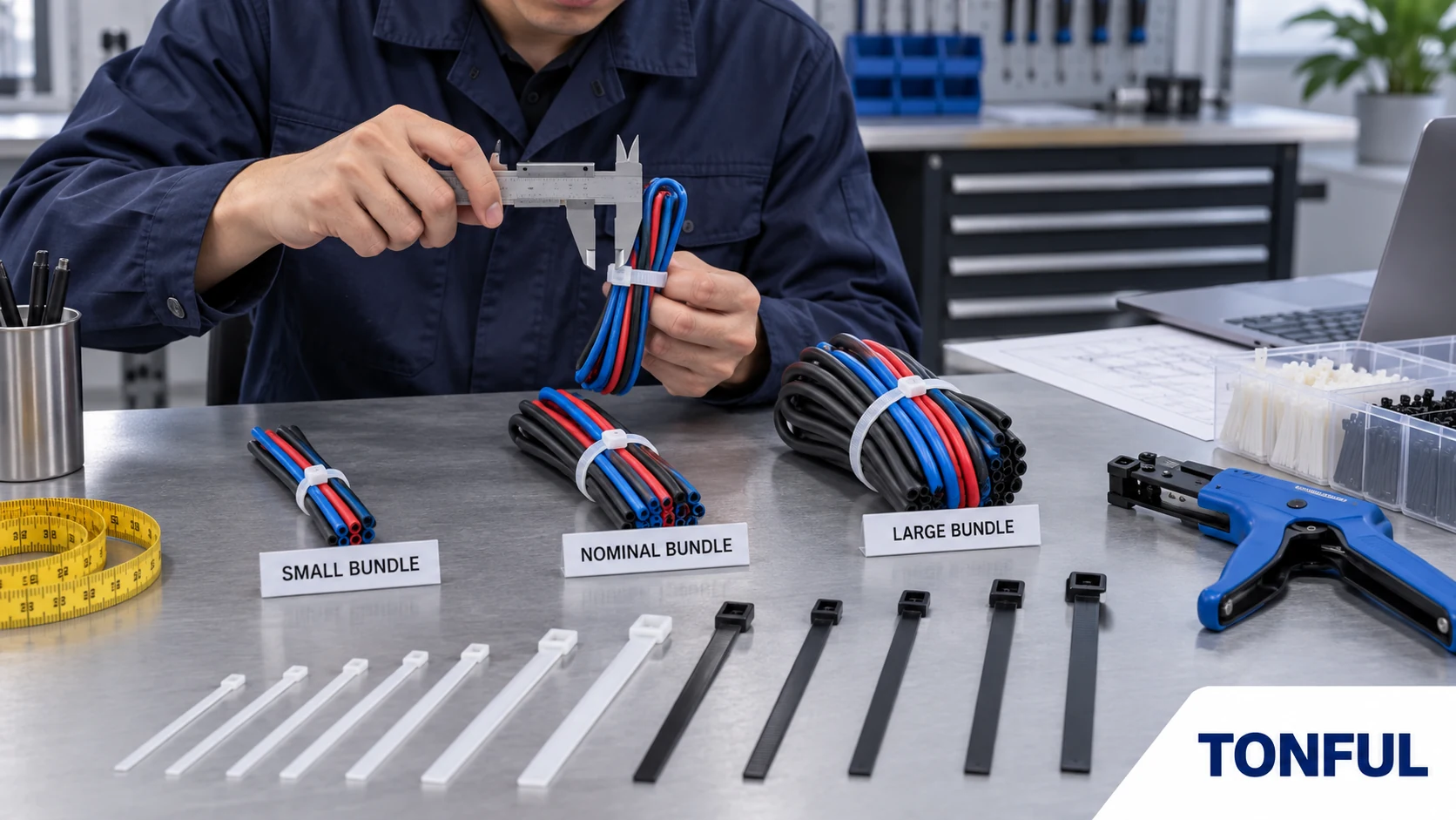
A cable tie can be long enough to wrap around a bundle and still be the wrong size. The usable strap may leave too little engagement, the head may collide with nearby components, the strap may be too wide for a routing slot, or the installed tension may damage insulation. Minimum loop tensile strength adds another decision, but it cannot replace dimensional fit or application testing.
This guide separates length, bundle diameter, width, head geometry and minimum loop tensile strength so engineers and buyers can specify each field correctly. It does not provide a universal size chart because product geometry, test conditioning and acceptance criteria differ. Use the exact drawing, applicable test method and production-intent assembly.
The Five Dimensions That Define Fit
| Selection field | What it controls | Common mistake |
|---|---|---|
| Overall length | Physical part envelope before installation | Treating it as usable wrap length |
| Usable strap length | Maximum practical loop and engagement | Ignoring head and tail allowance |
| Bundle diameter range | Smallest and largest approved closed loop | Calculating only the largest bundle |
| Strap width and thickness | Flexibility, contact area, routing clearance and tool choice | Selecting width only from a strength table |
| Head dimensions and orientation | Space, installation access and nearby interference | Checking the strap but not the head |
The official IEC 62275 scope covers metallic, non-metallic and composite cable ties and their fixing devices for wiring systems. Product classifications and tests belong to the applicable edition and exact product evidence; a family name or nominal dimension does not establish conformity.
Measure the Real Bundle
Use the Installed Cross-Section
Do not estimate bundle diameter by adding conductor diameters. Real bundles are rarely perfect circles, and corrugated conduit, braided sleeve, branch exits, overlaps and soft insulation change the cross-section. Measure representative production assemblies at the actual tie location. Record minimum, nominal and maximum conditions, including tolerances and optional circuits.
For a near-circular bundle, circumference can provide a useful check, but it is not a substitute for the supplier’s approved bundle range. For irregular bundles, use a flexible tape or a non-damaging trial loop to capture perimeter and shape. Photograph the measurement direction and identify the sample configuration.
The tie must also fit the smallest allowed bundle. A long tie around a small bundle may leave the head at an unstable angle or force the strap below its approved minimum loop. Check whether the tail can be inserted, tensioned and cut without contacting adjacent wires.
Include Assembly and Service Variation
Model insulation tolerance, sleeving, tape overlap, added circuits and the compression caused by installation. If the bundle changes with options, define separate approved configurations or select a range that covers all of them without excessive tightening. Where service personnel may add cables later, specify the permitted expansion and replacement rule instead of assuming spare tail length authorizes modification.
The broader cable tie application and material guide helps connect bundle measurement to environment and function. For mounting interfaces, use the edge-clip cable tie guide because panel retention is separate from loop fit.
Convert Bundle Size Into Tie Length
Overall Length Is Not Usable Length
A simple circumference calculation, C = pi x D, estimates the wrap around a circular bundle. The selected tie also needs head engagement, installation grip and any controlled tail required by the process. Head geometry consumes part of the nominal length, so do not add an arbitrary allowance and publish it as universal.
Use the supplier drawing’s usable bundle range whenever available. If only dimensions are supplied, build the maximum and minimum assemblies and confirm full locking engagement, tool access and cutoff. Record the engaged tooth region rather than accepting a loop that catches only at the edge of the locking range.
Avoid specifying a much longer tie solely to simplify inventory. Excess tail increases material and cutoff waste, can obstruct tools and may create sharp or loose remnants if the process is uncontrolled. One size can cover multiple bundles only when every configuration remains within its approved loop range and installation setting.
Head and Routing Clearance
Check head length, width and height against connector latches, ducts, covers, moving parts and neighboring tie locations. Define head orientation on the drawing when rotation could cause interference or abrasion. For automated installation, include presentation direction, tail geometry and tool access.
A narrow strap may pass through a slot while its head cannot. A wide strap may improve contact area but fail to bend around a small radius. The releasable cable tie guide illustrates why head function and service needs cannot be selected from length alone.

Conceptual dimension guide only; use the controlled product drawing for exact limits and tolerances.
Understand Minimum Loop Tensile Strength
What the Value Represents
Minimum loop tensile strength, often abbreviated MLTS, describes a minimum result for a closed cable-tie loop under a defined test method and conditioning state. It evaluates the assembled strap-and-lock system. It is not the raw material tensile strength, not a safe working load and not permission to suspend equipment unless the complete installation is approved for that purpose.
Test fixture geometry, loop diameter, pull direction, speed, specimen conditioning, temperature and failure definition can affect the result. Compare products only when methods and conditions are aligned. A higher catalog value measured under one method cannot automatically replace a lower requirement under another.
The final application can fail below an MLTS result because insulation crush, abrasion, panel retention, vibration or chemical aging governs first. Conversely, a tie does not need the highest available MLTS when the bundle only requires positioning and a larger strap would increase pressure or installation difficulty.
Select Strength From Loads and Risk
Define loads from harness weight, handling, acceleration, vibration, routing tension, maintenance and foreseeable disturbance. Separate steady load from shock or cyclic load. Identify how many ties share the load and whether their spacing and installation are controlled. Do not simply divide total mass by tie count; load distribution may be uneven, especially around bends or branch points.
Apply the safety or design factor required by the customer’s engineering rules, applicable standard or approved calculation. Do not invent a universal factor. If a cable tie is only securing cables to a separately approved support, state that function. If it is expected to support the wiring system, verify the applicable installation requirement and complete fixing arrangement.
For a focused explanation, see the cable tie tensile strength guide. The cable tie moisture and storage guide explains why nylon conditioning and handling must be identified when comparing results.
Avoid Bundle Damage From Excess Tension
Installation tension and MLTS are different. MLTS concerns failure of the closed tie under a defined test; installation tension controls how tightly the tie is applied. Increasing installation tension does not necessarily improve routing and can deform insulation, flatten data cables, restrict hose movement or transfer stress into connectors.
Define an installation tool and setting where repeatability matters. Validate it on minimum and maximum production bundles, including the softest insulation and most sensitive component. Inspect after installation and after relevant vibration, thermal or environmental conditioning. A flush cutoff must not leave a sharp projection or nick the head.
For data and telecom bundles, performance can be sensitive to deformation. For vehicle harnesses, controlled slack, strain relief and movement may matter more than maximum tightness. The correct criterion is the approved assembly condition, not “as tight as possible.”
Build a Size and Strength Specification
| Record field | Required entry |
|---|---|
| Application | Bundle location, function and routing drawing |
| Bundle configurations | Minimum, nominal and maximum measured cross-section |
| Tie dimensions | Overall/usable length, width, thickness and head envelope |
| Loop range | Approved minimum and maximum bundle diameter or perimeter |
| Material | Exact polymer grade/formulation or metal alloy/coating |
| Strength requirement | Property, method, conditioning and acceptance source |
| Installation | Tool, setting, orientation, cutoff and operator instruction |
| Environment | Temperature, UV, moisture, chemicals and vibration |
| Inspection | Dimensional, visual, functional and sample-test plan |
| Approval | Part/revision, sample IDs, evidence, approver and date |
Do not copy a competitor’s nominal dimensions or strength class without checking the actual assembly and intellectual-property boundaries. Define performance from the application’s needs, then qualify candidates against the same controlled record.
Plan the Loop Tensile Test
The test plan should state sample quantity and allocation, specimen lot, conditioning, fixture and mandrel geometry, test speed, equipment range, resolution and accuracy, calibration status, failure mode and acceptance source. Identify whether each sample is unaged, environmentally conditioned or part of a sequential test group. Retain an untested reference when useful.
Record peak result and failure location: strap break, tooth damage, pawl release, head fracture or fixture-related invalidity. Predetermine invalid-test and retest rules. A result caused by fixture slippage or setup error may be invalid, but an unfavorable valid result cannot be replaced silently.
| Sample ID | Part/lot | Conditioning | Loop/fixture | Speed | Peak result | Failure mode | Requirement source | Pass/fail |
|---|---|---|---|---|---|---|---|---|
| Enter ID | Enter traceability | Enter controlled state | Enter setup | Enter approved value | Record raw result | Record observation | Drawing/plan/standard | Record decision |

Conceptual test setup only—not an acceptance standard or traceable laboratory result.
Receiving and Change Control
Incoming checks should confirm part number, revision, lot, packaging, dimensions, head and strap geometry, material designation and representative locking function. Use calibrated equipment appropriate to the tolerance. Segregate mixed sizes, damaged packages, brittle samples, incomplete molding, deformed metal locks or inconsistent engagement.
Require review of changes to material, additives, color, dimensions, tooth or pawl geometry, metal alloy, coating, mold cavity, forming tool, conditioning, manufacturing site, test method and packaging. A familiar size code does not guarantee unchanged usable length or loop strength.
Work With TONFUL
TONFUL’s cable tie range includes multiple sizes, materials and head designs. Send the measured bundle range, routing drawing, space envelope, material/environment, strength requirement and method, installation tool, quantity and packaging needs. TONFUL can compare available drawings and production-intent samples; final approval remains tied to the documented assembly and test evidence.
