
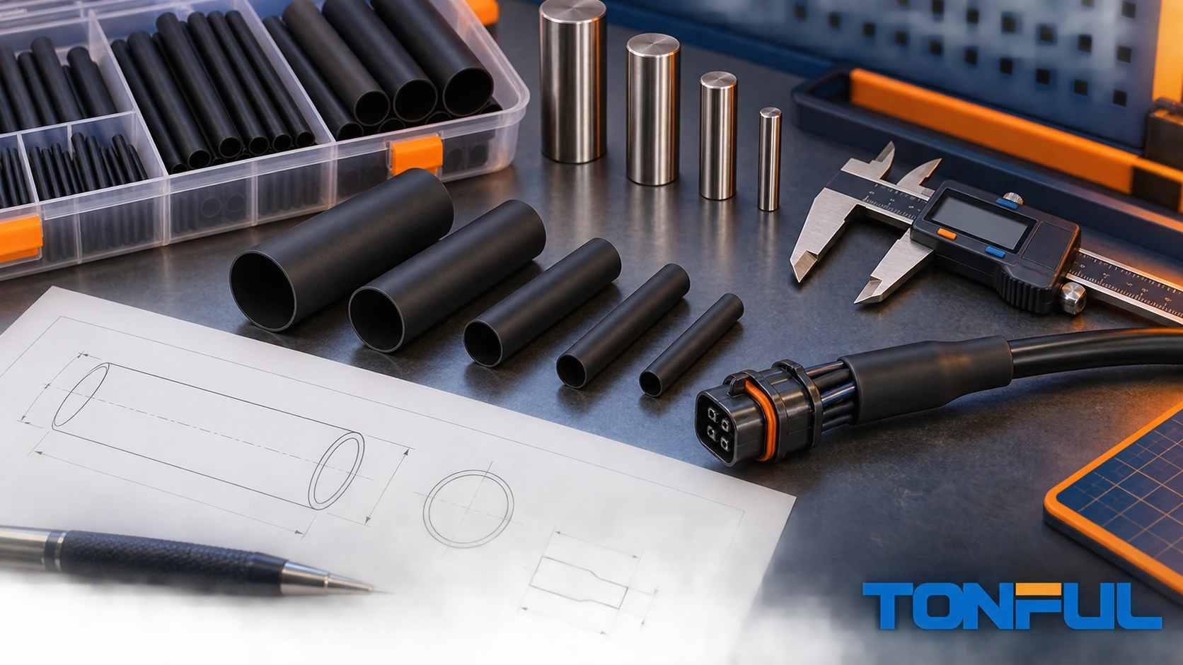
The correct heat shrink tubing size must pass over the largest part before heating and recover onto the smallest required surface afterward. Wire gauge alone cannot answer both questions because insulation thickness, splice barrels, connector bodies, terminals, bundle arrangement and manufacturing tolerances change the real outside diameter. The product’s supplied and recovered dimensions, not its nominal label, control fit.
This heat shrink tubing size guide provides a repeatable calculation and record format. It does not publish a universal AWG-to-tubing chart because such a chart can ignore insulation, connectors and product-specific tolerances. Use production-part measurements, the exact tubing drawing and a validated recovery process.
On this page: Required inputs | Fit equations | Worked example | Wall and length | Approval record
Collect the Required Sizing Inputs
Measure the Largest Pass-Over Feature
Measure every feature the unshrunk tube must cross: connector shell, terminal shoulder, splice barrel, solder joint, branch, label, braid transition or molded strain relief. Use the maximum outside diameter or controlling perimeter at the tightest orientation. An oval or rectangular feature may not pass through a circular tube simply because one dimension is smaller than the tube’s nominal ID.
Record tolerance, flash, keyways and assembly variation. If the tube is installed before crimping or connector assembly, document that process order because it can change the required supplied ID. Do not stretch tubing over a feature unless the product and process explicitly permit it; stretching can damage the tube or cause splitting during recovery.
Measure the Smallest Recovery Surface
Identify the smallest diameter where the installed tubing must grip, insulate or seal. On a splice, this may be the wire insulation beside a larger barrel. On a connector backshell, several wires may create an irregular bundle with valleys. Measure minimum production tolerance and the actual arrangement.
For adhesive-lined tubing, diameter fit is necessary but not sufficient. The liner must be compatible with the substrate, and the recovered geometry and heating process must support adhesive flow. A recovered ID smaller than the cable does not automatically prove a sealed interface.
The heat shrink tubing buying guide explains how sizing interacts with material, wall, environment and validation.
Read the Product Drawing Correctly
Heat shrink drawings commonly state a minimum expanded or supplied inside diameter and a maximum fully recovered inside diameter. These are directional limits. “Expanded ID minimum” means compliant supplied tubing should be at least that open. “Recovered ID maximum” means properly recovered tubing should not remain larger than that limit under the specified method.
Do not treat the nominal size as an exact measured ID. Soft tubing can become oval, stretch around a gauge or compress under calipers. TE Connectivity’s official measurement guide recommends measurement approaches that avoid distorting flexible tubing and notes that recovered wall should be measured after recovery.
Apply the Two Essential Fit Checks
Let:
D_pass_max= maximum diameter or equivalent geometry the supplied tube must pass over.ID_exp_min= minimum expanded inside diameter from the product drawing.D_sub_min= minimum substrate diameter at the final recovery location.ID_rec_max= maximum fully recovered inside diameter from the product drawing.C_install= installation clearance required by the approved process.
Check 1: Supplied Tube Must Pass Over the Assembly
The basic pass-over condition is:
ID_exp_min >= D_pass_max + C_install
Clearance is not a universal percentage. It depends on tube stiffness, length, surface friction, geometry, temperature and assembly method. Establish it with representative parts. Using the guaranteed minimum expanded ID protects against selecting from one unusually loose sample.
Check 2: Tube Must Retain Recovery on the Smallest Surface
The basic recovery condition is:
ID_rec_max < D_sub_min
This confirms that the tube has theoretical recovery available at the smallest substrate. It does not prove the installed wall, grip, adhesive wetting or environmental seal. The product should normally retain a controlled amount of unrecovered capability rather than being selected exactly at its limit.
TE Connectivity’s correct-size tubing guide describes a method that seeks meaningful recovery while retaining some unresolved recovery after installation. Use its principle as guidance, but apply the installation window and margins approved for the exact product and project.

The two checks use controlled drawing limits; they do not replace assembly validation.
Illustrative Calculation
Assume a development assembly has these measured tolerance limits:
- Largest connector feature:
11.2 mm. - Process-approved installation clearance:
0.8 mm. - Smallest cable diameter at the recovery surface:
4.6 mm.
The supplied tube must therefore have:
ID_exp_min >= 11.2 + 0.8 = 12.0 mm
The recovered limit must satisfy:
ID_rec_max < 4.6 mm
A candidate drawing showing ID_exp_min = 12.0 mm and ID_rec_max = 4.0 mm passes these two preliminary dimensional checks. It is not yet approved. Engineering must still review recovered wall, material, longitudinal change, adhesive, heating, bend transition and required assembly tests.
This example is illustrative, not a recommendation for a specific wire, connector or TONFUL part number. Substitute controlled project measurements and product limits in the calculator fields.
| Calculator input | Project value | Source |
|---|---|---|
Maximum pass-over feature, D_pass_max |
Enter value | Tolerance drawing or measured production parts |
Installation clearance, C_install |
Enter value | Approved assembly trial |
| Required minimum expanded ID | Auto-calculate | D_pass_max + C_install |
Minimum recovery substrate, D_sub_min |
Enter value | Tolerance drawing or measured production parts |
| Candidate expanded ID minimum | Enter value | Tubing drawing |
| Candidate recovered ID maximum | Enter value | Tubing drawing |
| Pass-over result | Pass/Fail | Expanded-ID comparison |
| Recovery result | Pass/Fail | Recovered-ID comparison |
The current TONFUL heat shrink sizing page should be refreshed around this two-boundary method rather than publishing another competing sizing URL.

Enter project measurements and exact product-drawing limits; the blank worksheet contains no assumed approval values.
Use Ratio as a Result, Not the Only Input
The nominal shrink ratio is approximately the relationship between expanded and recovered diameters for a product family. It helps screen whether a tube can span a large transition. It does not replace the exact dimensions.
A “3:1” label does not guarantee that every supplied diameter or recovered diameter needed by a project exists. Two 3:1 families can differ in wall, adhesive, stiffness, tolerance and available sizes. Verify the size table and drawing. The heat shrink ratio guide explains 2:1, 3:1 and 4:1 behavior; overlapping ratio articles should be consolidated into one maintained resource.
High ratio can reduce the number of inventory sizes, but it can also increase recovery travel, cycle time, wall build and sensitivity to uneven heating. Select the lowest ratio that safely accommodates controlled geometry and performance, unless another project requirement justifies a different choice.
Include Wall Thickness and Longitudinal Change
Recovered Wall Thickness
Recovered wall is measured under the product’s defined recovery method. Installed wall on a real substrate can differ because the tube stops before free recovery. Do not subtract recovered ID from expanded ID to estimate wall; polymer volume, longitudinal change, tolerance and multilayer construction make that shortcut unreliable.
Specify the wall property required by the application and confirm it through the product drawing and assembly validation. For dual-wall tubing, distinguish total recovered wall, outer wall and adhesive layer where the documentation provides them. A thicker wall can improve mechanical protection but add stiffness, weight and heating demand.
Longitudinal Change
Heat shrink tubing can shorten or, for some products, change length in another direction during recovery. Use the drawing’s longitudinal-change limit when choosing cut length. The minimum cut length can be represented as:
Cut length >= required final coverage / (1 - maximum fractional shortening)
If the product permits 10% maximum shortening and the required final coverage is 90 mm, the preliminary cut length is at least 90 / 0.90 = 100 mm. This mathematical example is not a universal 10% allowance; use the actual product limit and add project-specific positioning tolerance.
Longitudinal movement can uncover splice edges, move printed text, pull adhesive away from a sealing land or create an overly stiff transition. Validate minimum and maximum cut lengths on tolerance-limit assemblies.

Apply the selected product’s longitudinal-change limit when converting required final coverage into cut length.
Consider Irregular and Multi-Diameter Geometry
Round diameter checks do not fully describe rectangular busbars, oval bundles, connector keys or multi-wire valleys. For a non-round pass-over feature, use a physical fit study, perimeter analysis or approved gauge. Check whether the tube folds, bridges or traps air during recovery.
For a bundle, arrange wires as they will be produced and account for tie points, branches and tolerance. Adhesive may flow into some valleys while leaving others open. If sealing matters, section development samples or use the specified leakage or ingress test rather than relying only on external appearance.
The single-wall versus dual-wall guide helps determine whether the selected geometry also needs an internal adhesive.
Sizing and Sample Approval Record
| Record field | Required entry |
|---|---|
| Assembly identity | Drawing, revision, wire/connector and configuration |
| Measured parts | Sample IDs, quantity, instruments and tolerance extremes |
| Pass-over geometry | Maximum diameter/perimeter, orientation and clearance |
| Recovery surface | Minimum diameter and substrate material |
| Tubing identity | Manufacturer, family, part number, size, ratio, wall and color |
| Drawing dimensions | Expanded ID min, recovered ID max, wall and longitudinal change |
| Installation process | Equipment, fixture, heating sequence and endpoint |
| Results | Fit, position, defects, wall/adhesive observations and tests |
| Decision | Approved scope, deviations, reviewer and date |
Sample approval should include the size and product construction that production will receive. A successful fit with one loose connector or oversized wire does not approve the tolerance range. Incoming inspection should verify identity and use a measurement method that does not distort the tube.
Review candidate supply families on the TONFUL heat shrink tubing page, then request the exact dimensional drawing before completing this record.
Discuss Heat Shrink Sizing With TONFUL
Send TONFUL the largest pass-over geometry, smallest recovery diameter, tolerance range, required coverage, substrate materials, wall or adhesive need, environment, color or printing and quantity. TONFUL can discuss candidate sizes and samples within its documented range. Final approval should use the exact drawing and a verified production assembly.
