
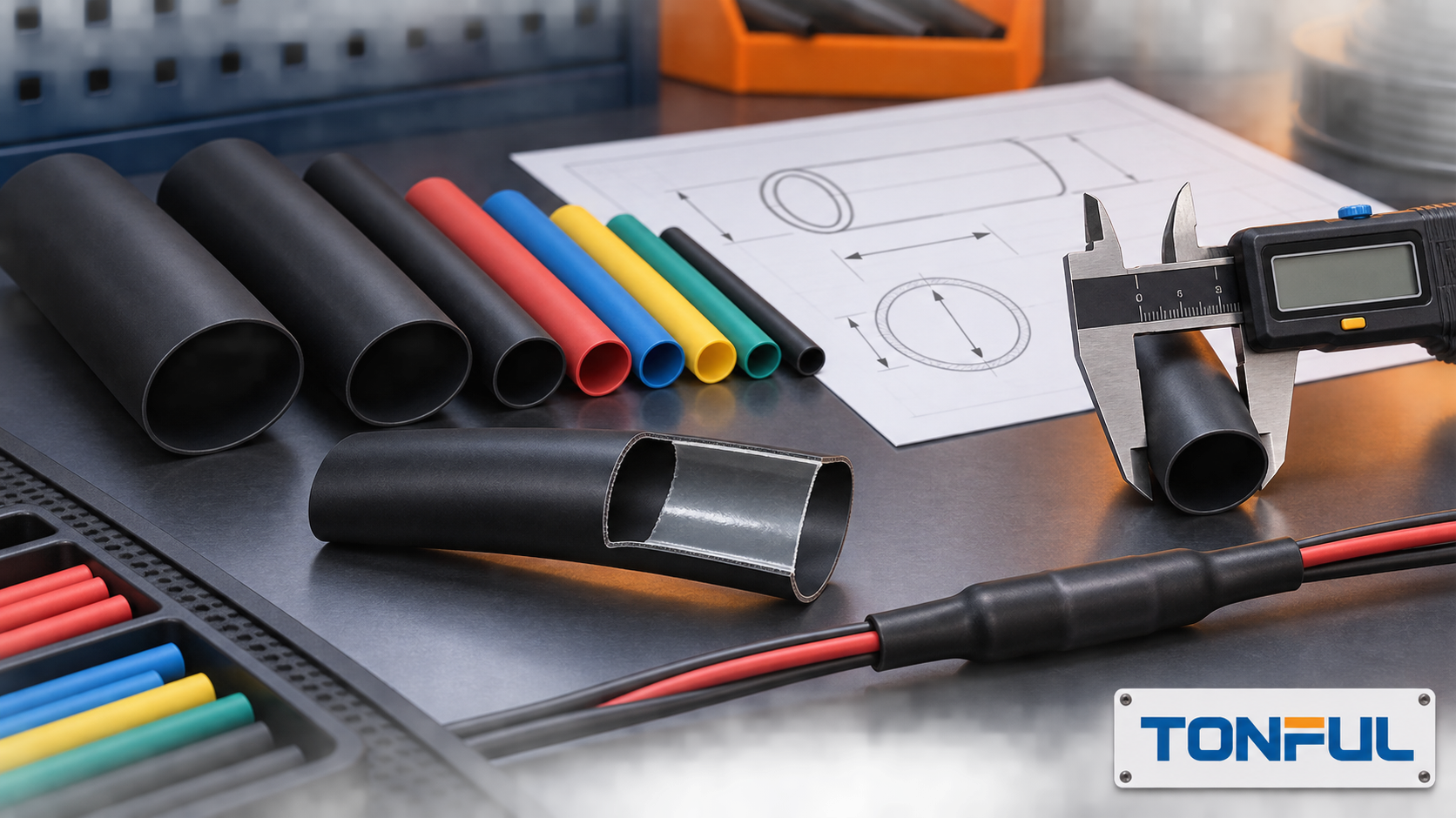
Heat shrink tubing should not be selected from color, nominal diameter or shrink ratio alone. A usable specification must fit over the largest feature before heating, recover onto the smallest required substrate, tolerate the installation process and remain suitable for the electrical, mechanical and environmental conditions of the finished assembly. The drawing, product data and approved validation plan must all describe the same tubing family and size.
This guide gives engineers, harness manufacturers and procurement teams a practical selection sequence. It does not assign universal temperature, voltage, flame, sealing or service-life values. Those limits vary by product and test method. Request model-level data and approve representative samples rather than extending one result to a material category.
On this page: Define the application | Choose construction | Choose material | Calculate size | Validate evidence
Define the Application Before Selecting Tubing
Identify the Tubing’s Actual Job
Begin with the function. Heat shrink may provide electrical insulation, color identification, abrasion protection, bundle organization, strain transition, splice covering, connector-backshell protection or environmental sealing. These functions are related but not interchangeable. A thin identification sleeve is not automatically a durable cable-repair jacket, while thick adhesive-lined tubing may be unsuitable where flexibility, low profile or future removal matters.
Record the substrate beneath the tube: insulated wire, cable jacket, metal terminal, molded connector, braided shield, busbar, hose or mixed-material transition. Note sharp edges, steps, branches and differences between the largest pass-over diameter and the smallest sealing diameter. A tube that fits the straight cable may not pass over a connector. A high-ratio product may bridge that geometry, but ratio alone does not prove adhesive compatibility, installed wall, electrical performance or bend suitability.
The TONFUL heat shrink tubing range presents material and construction options for project discussion. Treat the page as a starting point and confirm the exact series, dimensions and evidence before release.

Conceptual selection workflow; final approval must use the controlled product drawing and project requirements.
Map the Service Environment
List service temperatures, installation heat, vibration, abrasion, sunlight, water, salt, fuels, oils and cleaners. Distinguish splash, weather exposure, pressure washing and immersion. Adhesive can improve protection on clean compatible substrates, but does not independently establish an IP rating. For electrical use, define whether the tube is supplementary protection, controlled insulation or part of a qualified accessory system. Never derive system voltage solely from polymer dielectric strength.
Choose Wall Construction and Sealing
Single-Wall Tubing
Single-wall tubing has one polymer wall and is commonly considered where low profile, flexibility, identification or general insulation is needed. Selection still depends on exact material and product data. Verify supplied and recovered dimensions, recovered wall, longitudinal change, recovery conditions, operating range, fluid response and any requested flame or agency evidence.
Single-wall tubing does not normally fill irregular gaps at its ends. It can conform closely to a uniform substrate, but close contact should not be described as a sealed joint without an appropriate assembly test. The single-wall versus dual-wall guide should be used when the project must balance profile, flexibility, sealing and rework.
Dual-Wall and Adhesive-Lined Tubing
Dual-wall tubing combines an outer recoverable layer with an inner adhesive or sealant. During controlled heating, the outer layer recovers and the liner softens and flows. The design can help protect splices, cable ends and connector transitions, provided the adhesive is suitable for the wire insulation, cable jacket, metal or molded substrate.
Specify the adhesive type, minimum and maximum substrate diameters, surface preparation, overlap, permitted voids and visual process indicators. A small adhesive bead may show that flow occurred, but it does not prove that every internal void was filled. Highly irregular bundles, contamination, trapped air, insufficient heating and incompatible low-surface-energy materials can all limit sealing. Where sealing is critical, validate the completed joint under the applicable conditioning and leakage or ingress method.

Conceptual illustration only—not an acceptance standard or laboratory cross-section.
Thin, Medium and Heavy Walls
Wall descriptions are product-family terms, not universal thickness classes. Thin-wall products favor compact installations and flexibility. Medium- and heavy-wall constructions can add mechanical protection, installed wall and adhesive volume, but require more heating energy and may create stiffer transitions. For underground cable or busbar work, use the controlled accessory specification and system design rather than substituting a general-purpose tube because it looks thick.
Select Material From the Real Environment
Material selection begins with the exact compound and construction, not a generic polymer reputation.
| Material family | Typical reason to evaluate it | Evidence to request | Selection warning |
|---|---|---|---|
| Cross-linked polyolefin | Broad general-purpose, harness and adhesive-lined availability | Product drawing, temperature conditions, fluids, dimensions and flame evidence | Not every polyolefin grade has the same temperature, UV or fluid performance |
| PVC | Flexible covering, packaging or selected electrical applications | Plasticizer system, operating and recovery conditions, flame and regulatory data | Do not transfer polyolefin processing assumptions to PVC |
| PTFE | Elevated temperature, chemical exposure and low-friction needs | Exact type, expansion/recovery method, dimensions and qualification documents | Recovery conditions may be much higher than nearby components tolerate |
| FEP | Transparent covering and selected chemical or temperature applications | Optical, dimensional, recovery and fluid data | Transparency does not prove a universal electrical or medical approval |
| PVDF | Abrasion, flame or chemical performance in selected designs | Grade, test reports, temperature and dimensional data | Product-specific evidence remains necessary |
| Silicone | Flexibility across a broad temperature range in suitable formulations | Hardness, tear, dimensions, environment and any application-specific evidence | Softness can affect handling and mechanical protection |
| Fluoroelastomer | Fuel, oil and elevated-temperature environments where qualified | Polymer identity, fluid aging, temperature and source documentation | A trade name or material label alone does not prove performance |
Do not compare only maximum temperature. Separate continuous operating range, short-duration exposure, minimum shrink onset and full-recovery process conditions. A tube can survive the final environment yet require an installation temperature that damages insulation, seals, electronics or adhesive nearby. Conversely, heating only to the lower onset temperature may leave incomplete recovery.
Use the heat shrink tubing material guide for a deeper comparison, then confirm the actual product specification and sample.
Select Size and Shrink Ratio
Measure Every Critical Diameter
Measure the largest feature the supplied tube must pass over and the smallest feature it must recover onto. Include connector keys, terminal shoulders, splice barrels, bundle tolerances, labels and branch geometry. Measurements should represent production parts and worst-case tolerances, not one convenient sample.
Manufacturers commonly specify a minimum expanded inside diameter and a maximum fully recovered inside diameter. Use those controlled limits. Do not assume a loose sample’s measured inside diameter is the guaranteed supplied size, and do not use a nominal ratio as a substitute for the dimensional table.
TE Connectivity’s official tubing size selection guide recommends selecting tubing that undergoes meaningful recovery while retaining some unresolved recovery after installation. Its worked guidance is useful as a method, but the approved installation window must come from the selected product and project requirements.

Use the minimum expanded ID, maximum recovered ID and longitudinal-change limit from the selected product drawing.
Understand What the Ratio Does and Does Not Mean
The nominal shrink ratio is the relationship between supplied and recovered diameters for a product family. A 2:1 tube suits relatively uniform geometry; 3:1 or 4:1 products can span larger diameter transitions. A 6:1 claim must be tied to a real series and dimensional table. Higher ratio is not automatically better: it can change wall build, adhesive volume, stiffness, heating time, inventory cost and the risk of uneven recovery.
For example, a connector body may require a large supplied ID while the cable requires a small recovered ID. The candidate passes the first dimensional check only if the guaranteed expanded ID clears the connector and the recovered ID can develop the intended fit on the cable. Engineering must then evaluate wall construction, adhesive flow, longitudinal movement and the completed transition. The heat shrink ratio guide explains the ratio calculation; duplicate ratio content should be consolidated into one maintained English reference.
Account for Recovered Wall and Length Change
Wall thickness should be evaluated in the recovered condition specified by the product method. A tube installed partway through its recovery range may not have the same wall as a fully recovered laboratory specimen. Longitudinal change can shift coverage away from a splice edge or printed identifier. Use the product’s stated longitudinal-change limit and qualify the cut length on representative assemblies.
Define the Installation Process
The approved process should specify heating equipment, fixtures, orientation, starting point, motion, exposure control and endpoint. A heat gun is flexible for prototypes and field work but depends strongly on operator technique. Ovens can improve circumferential uniformity for suitable production parts. Infrared systems can support controlled automation but require validation of absorption, shadowing and line speed.
Inspect for complete recovery, correct position, scorching, splits, holes, trapped air, excessive wrinkles, adhesive displacement, exposed sharp edges and legible marking. Do not use an open flame as the default production method: soot, concentrated heat and ignition risk make the process difficult to control. Never heat near energized equipment, flammable vapor or heat-sensitive components without an approved safety procedure.
Build a Repeatable Process Window
A production instruction should identify the tubing part number and lot, cut length, assembly, equipment, fixture, heating sequence and inspection result. Establish the process on minimum- and maximum-tolerance substrates. Check whether metal terminals draw away heat, nearby polymers reach their limits or long sleeves recover unevenly. Separate qualification tests from routine checks, and use visual features only after validation has shown what they mean for the specific geometry.
Compare Commercial Offers on the Same Basis
Compare accepted installed cost, not price per meter. Include usable yield, cutting, setup, recovery time, inspection, rejection, rework and requalification after change. The quotation should identify product revision, packaging, minimum order quantity, price breaks, sample terms, lead time and change notification without assuming fixed TONFUL terms. The bulk heat shrink tubing sourcing guide provides the wider supplier-control workflow.
Validate the Product and Supplier
UL Solutions explains that its insulating tubing certification program evaluates submitted products for applicable electrical, mechanical and flammability requirements, including heat-shrinkable constructions and meltable liners. This does not mean every heat shrink product is UL certified. Request the exact category, file, recognized designation, color, size range and conditions that cover the offered item.
Apply the same discipline to other claims. RoHS and REACH documentation addresses restricted substances and chemical obligations; it is not a flame rating. CE marking is not interchangeable with third-party component certification. VW-1 and UL 94 V-0 refer to different evaluation contexts and should not be presented as equivalent. An IP claim must identify the tested completed assembly, installation and report.
Before approval, obtain and reconcile:
- Manufacturer and exact part number, material, construction and color.
- Drawing revision with minimum expanded ID, maximum recovered ID, recovered wall and longitudinal change.
- Operating and installation temperature definitions.
- Fluid, UV, flame, electrical and mechanical evidence required by the project.
- Lot identification, certificate requirements and change-notification rules.
- Representative samples for fit, recovery, process-window and completed-assembly testing.
- Packaging, spool or cut-length controls, printing requirements and storage instructions.
For incoming inspection, check labels and lot identity before dimensions. Use suitable plug gauges or a defined measurement method that does not stretch soft tubing. Verify recovered dimensions only after conditioning and recovery according to the controlled method. TE’s single-wall measurement guide explains why deforming a soft tube with ordinary measurement pressure can create misleading readings.
Release Checklist
| Decision field | Required project entry |
|---|---|
| Function | Insulation, identification, abrasion, strain transition, sealing or qualified accessory function |
| Substrate | Materials, minimum/maximum diameters, sharp edges and pass-over geometry |
| Tubing identity | Manufacturer, series, part number, material, wall type, adhesive and color |
| Dimensions | Expanded ID minimum, recovered ID maximum, recovered wall and longitudinal change |
| Environment | Temperature, fluids, water, UV, abrasion, vibration and flexing |
| Electrical/flame | Applicable requirement, exact test or certification, covered model and evidence ID |
| Process | Equipment, temperature controls, fixtures, endpoint and visual acceptance |
| Validation | Sample quantity, conditioning, assembly tests, acceptance source and approver |
| Supply control | Lot traceability, packaging, storage, shelf-life basis and change notification |
Release only the tested scope. A sample approved on one wire insulation, connector geometry or heat process does not automatically approve other materials and sizes. If evidence conflicts, stop the release and resolve the drawing, certificate, sample identity and application record rather than selecting the most convenient source.
Discuss a Heat Shrink Tubing Project With TONFUL
Send TONFUL the substrate diameter range, largest pass-over feature, material and wall preference, temperature and fluid exposure, required evidence, color or printing, cut length, packaging and estimated volume. TONFUL can discuss an appropriate product and sample plan within the documented supply range. Final approval should remain tied to the controlled drawing, project requirements and validated production assembly.