
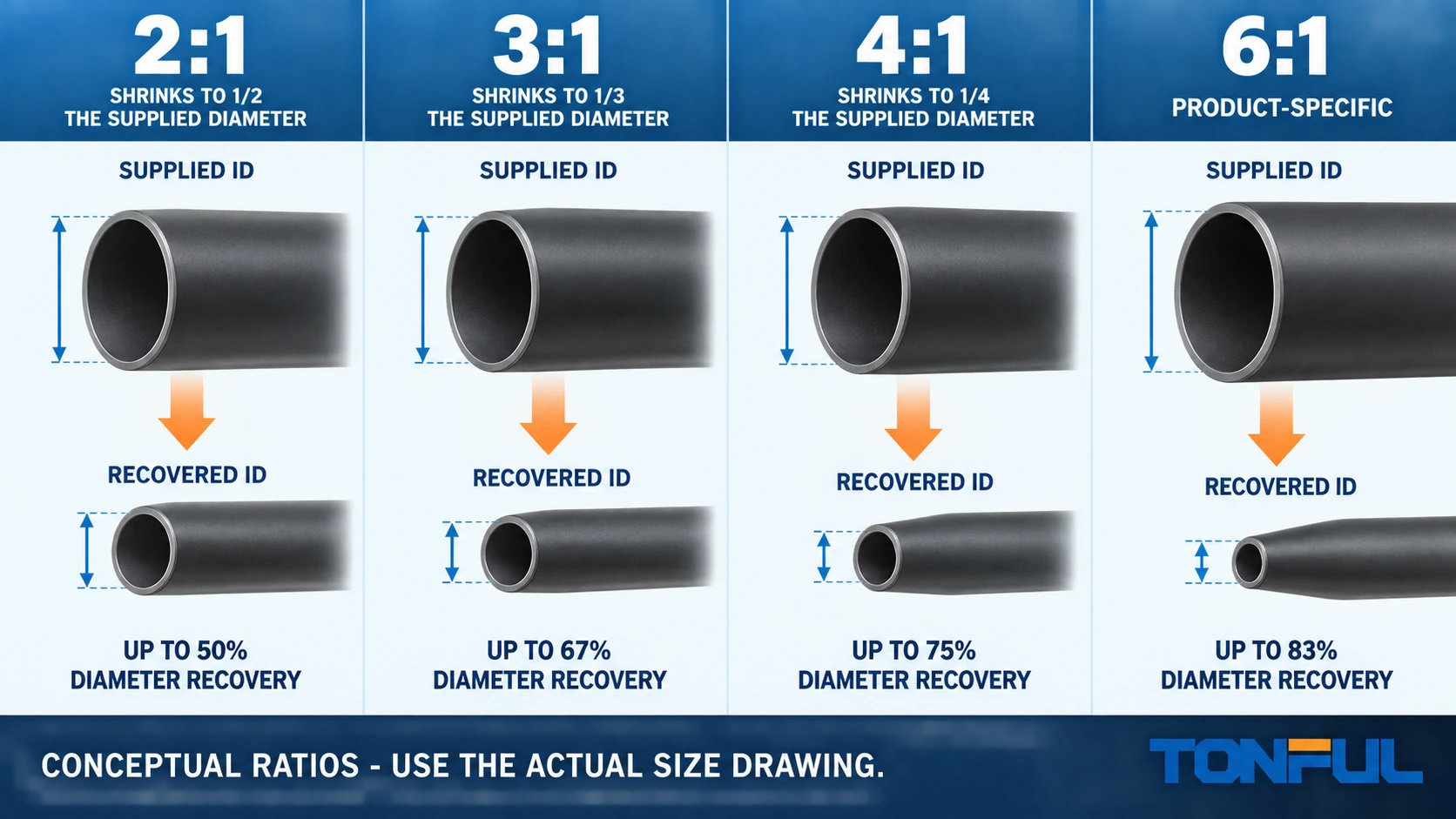
A heat shrink ratio describes the relationship between a tubing family’s expanded and fully recovered diameters. It helps engineers estimate how large a feature the tube can pass over and how small a substrate it can recover toward. It does not define the actual size, installed wall, adhesive, material, temperature, sealing or electrical performance.
This guide compares 2:1, 3:1, 4:1 and conditional 6:1 heat shrink tubing without treating the highest ratio as the best choice. Final selection must use the exact product drawing: minimum expanded inside diameter, maximum recovered inside diameter, recovered wall and longitudinal-change limit.
On this page: Ratio calculation | 2:1 | 3:1 | 4:1 | 6:1 | Decision matrix | Approval
What the Shrink Ratio Means
The nominal relationship is:
Shrink ratio = expanded inside diameter / fully recovered inside diameter
An idealized 12 mm expanded tube recovering to 6 mm has a 2:1 ratio. A 12 mm tube recovering to 4 mm has a 3:1 ratio. These calculations explain the label, but catalog products use dimensional limits and tolerances. A compliant drawing may specify an expanded ID minimum and a recovered ID maximum rather than two exact diameters.
Use ratio to screen product families, then perform two separate checks:
- The guaranteed expanded ID must clear the largest connector, terminal, splice or branch plus approved installation clearance.
- The guaranteed recovered ID must be smaller than the minimum substrate diameter where recovery, grip or adhesive compression is required.
The heat shrink tubing size guide and calculator should provide the controlled sizing method. Ratio alone cannot approve a fit.

Conceptual ratio samples; use the actual product drawing for dimensional selection.
2:1 Heat Shrink Tubing
Where 2:1 Is Efficient
Two-to-one tubing is commonly evaluated for relatively uniform wire, cable, component and bundle diameters. It can be economical, widely available and fast to recover because it travels through a smaller diameter range than a higher-ratio product. It may be suitable for insulation, color coding, identification and mechanical protection when the supplied tube can already pass over the assembly.
Use actual dimensions. A 2:1 family with the correct nominal label can still fail if its minimum expanded ID does not clear a terminal shoulder or its recovered ID is too large for the smallest wire.
Limits of 2:1
A large difference between connector and cable diameters can fall outside a 2:1 size. Selecting a much larger tube to clear the connector may leave insufficient recovery on the cable. Do not force the supplied tube over a feature, and do not assume that reaching the catalog’s fully recovered condition on one section guarantees a uniform transition.
3:1 Heat Shrink Tubing
Why 3:1 Covers Wider Transitions
Three-to-one tubing can pass over a larger feature while recovering toward a smaller cable or bundle. It is frequently considered for splices, terminals, connector tails and adhesive-lined assemblies. A wider diameter window can also reduce the number of sizes held in inventory.
Those benefits must be balanced against construction. Many 3:1 products are adhesive-lined, but “3:1” itself does not mean dual wall or waterproof. Confirm outer material, liner, wall, dimensions and evidence.
Process Considerations
Greater recovery travel can require more controlled heating. Start from the process location defined by the work instruction and move heat to avoid trapping air or forcing adhesive in the wrong direction. Validate the transition on minimum and maximum substrate tolerances. Check that recovered stiffness does not create a harmful bend point beside the sleeve.
The single-wall versus dual-wall heat shrink guide separates ratio from wall construction and sealing function.
4:1 Heat Shrink Tubing
Applications With Large Diameter Differences
Four-to-one tubing is evaluated where a tube must clear a bulky connector, irregular component or large splice and still recover onto a substantially smaller cable. It can simplify installation where removing the connector is impractical. It may also consolidate several lower-ratio inventory sizes.
The ratio does not eliminate geometry limits. Long keys, rectangular flanges, sharp edges and multiple branches can prevent installation or cause folding. Measure the maximum perimeter and orientation, not only one diameter.
Wall, Adhesive and Heating
A high-ratio product can build a substantial recovered wall or contain more adhesive than a lower-ratio alternative. That may support mechanical protection but can increase stiffness, weight, heating energy and cycle time. Excessive local heat can scorch the outer wall while the inner region remains incompletely recovered around a metal heat sink.
Use product-specific installation instructions and inspect the complete joint. An adhesive bead can be a process indicator only after validation links it to internal coverage for that geometry.
6:1 Heat Shrink Tubing
Six-to-one tubing should be treated as a product-specific option, not a standard capability that can be assumed from a supplier’s general range. Require a real series, size table, drawing and samples. Verify the expanded ID, recovered ID, wall, construction, length change, material and installation conditions.
The wide transition may solve unusual pass-over problems, but it can create a demanding recovery process and a thick or stiff final assembly. Before selecting 6:1, check whether a molded boot, breakout, wraparound sleeve, connector backshell or assembly-sequence change provides a better controlled solution.
The TONFUL heat shrink tubing page can be used to discuss available ratios, but a general “up to 6:1” statement must never replace model-level evidence.
Worked Diameter Examples
Example A: Uniform Cable
A cable tolerance range is 5.4–5.8 mm and the tube does not pass over a larger component. A candidate with minimum expanded ID above the maximum cable diameter and maximum recovered ID below the minimum cable diameter can pass the preliminary fit checks. A 2:1 product may be sufficient; choosing 4:1 provides no automatic performance benefit.
Example B: Connector-to-Cable Transition
A connector feature is 17.0 mm maximum, approved installation clearance is 1.0 mm and the cable is 6.2 mm minimum. The candidate needs expanded ID of at least 18.0 mm and recovered ID below 6.2 mm. A nominal 3:1 label might suggest a candidate, but only the actual drawing decides. A listed 18/6 product and a 24/8 product do not satisfy the same boundary even if both are marketed within a similar ratio family.
Example C: Large Irregular Feature
A rectangular connector has a diagonal and key that exceed its nominal shell diameter. Calculate neither 4:1 nor 6:1 from the cable alone. Use a fit gauge or sample installation at the worst orientation, inspect for stretching and sharp-edge damage, then verify recovery on the cable and the completed environmental or mechanical requirement.
All three examples are illustrative. They are not size recommendations or acceptance limits for a TONFUL product.

Verify pass-over clearance and recovered fit with controlled drawing limits and production geometry.
Ratio Selection Matrix
| Ratio family | Typical geometry reason | Main benefit | Main verification risk |
|---|---|---|---|
| 2:1 | Relatively uniform wire, cable or component | Simple sizing, broad availability, shorter recovery travel | May not bridge a connector-to-wire transition |
| 3:1 | Moderate splice, terminal or connector transition | Wider fit range and possible inventory reduction | Ratio mistaken for proof of adhesive sealing |
| 4:1 | Large pass-over feature with smaller recovery surface | Covers substantial diameter difference | Wall build, stiffness, heating and irregular geometry |
| 6:1 | Exceptional transition supported by a real product | Very wide recovery range | Availability, process control and excessive installed bulk |
Select the lowest ratio that meets controlled geometry and performance with acceptable process margin. This is an engineering starting point, not a rule that overrides the approved product drawing.

Higher ratio is not automatically better; each row identifies a different verification focus.
Ratio Does Not Define Installed Performance
The same ratio can be offered in different materials, colors, wall classes and adhesive systems. Therefore, never use ratio as evidence for:
Use the heat shrink tubing material guide when the geometry is known but temperature, fluid or process requirements still determine the polymer family.
- Continuous operating temperature or full-recovery temperature.
- Flame, smoke, halogen or agency status.
- Voltage rating or dielectric performance of the completed system.
- Fluid, UV, abrasion or chemical resistance.
- Waterproofing, IP rating or long-term environmental sealing.
- Recovered wall thickness or bend stiffness.
- Shelf life, adhesive compatibility or storage conditions.
UL Solutions’ insulating tubing certification overview explains that submitted tubing products are evaluated for applicable electrical, mechanical and flammability requirements. Verify recognition for the exact product; the ratio is only one construction attribute.
Verify the Complete Product
Record the manufacturer, series, part number, material, wall type, adhesive, color, ratio, expanded ID minimum, recovered ID maximum, recovered wall, longitudinal change and recovery conditions. Link every requested certification or test to the exact designation.
Then validate production geometry and process:
- Minimum and maximum substrate tolerances.
- Largest pass-over feature and installation clearance.
- Heating equipment, fixture, sequence and endpoint.
- Position, final coverage and longitudinal movement.
- Wrinkles, splits, scorching, voids and adhesive distribution.
- Required electrical, mechanical or environmental assembly tests.
For bulk purchasing, the bulk heat shrink tubing sourcing guide adds lot traceability, packaging and change-control requirements.
Consolidate TONFUL Ratio Content
TONFUL currently has overlapping ratio pages. Keep the URL with the stronger search history, rewrite it using this evidence-based comparison and redirect weaker English duplicates. Translated versions should use correct hreflang rather than competing as separate English sources. One maintained ratio guide will improve clarity and reduce contradictory examples.
Discuss Heat Shrink Ratios With TONFUL
Send TONFUL the largest pass-over geometry, smallest recovery surface, tolerance range, material and wall preference, adhesive need, environment, required evidence and quantity. TONFUL can discuss candidate product families and samples within its documented range. Final approval must name the exact size and validated process, not only a ratio.
