
Automotive heat shrink tubing should be selected for a defined harness location and function, not from a generic “automotive grade” label. A sleeve inside a dry passenger compartment does not face the same heat, fluids, vibration, abrasion or water paths as tubing near an engine, door hinge, wheel area or underbody splice. The product also must fit the actual terminal, wire insulation, connector and production heating process.
This guide shows how to translate vehicle location into material, construction and validation requirements. It does not provide universal temperature, voltage, fluid or cycle limits. Those values must come from the customer drawing, OEM specification, applicable standard edition and approved test plan for the exact assembly.
On this page: Location | Material | Heat and fluids | Abrasion | Sealing | Validation
Classify the Vehicle Mounting Location
Begin with the harness route and local conditions. Record whether the tube is in the cabin, instrument panel, seat, roof, door, trunk, engine compartment, battery area, chassis, wheel area or underbody. Note proximity to heat sources, moving parts, edges, clips, connectors, drains and fluid service points. The same vehicle can contain several different environments.
| Mounting area | Typical design concerns | Evidence to request |
|---|---|---|
| Cabin or instrument panel | Fit, identification, flame requirement, squeak/rattle and serviceability | Drawing, material and applicable interior requirements |
| Door or tailgate | Repeated flexing, water paths, window mechanisms and tight bend zones | Dynamic harness test and sealing/abrasion evidence |
| Engine compartment | Heat, oil/fuel/coolant exposure, vibration and crowded routing | Location-specific thermal, fluid and mechanical plan |
| Chassis or underbody | Water, salt, stone impact, abrasion and temperature cycling | Assembly environmental and mechanical validation |
| Battery or high-current area | Electrical insulation, heat, chemicals, spacing and color identification | Electrical design and system-level approval documents |
Do not infer requirements only from a vehicle platform name. Confirm market, powertrain, model year, harness revision, mounting orientation and nearby components. A routing change can move tubing closer to a hot surface or sharp bracket without changing the sleeve part number.

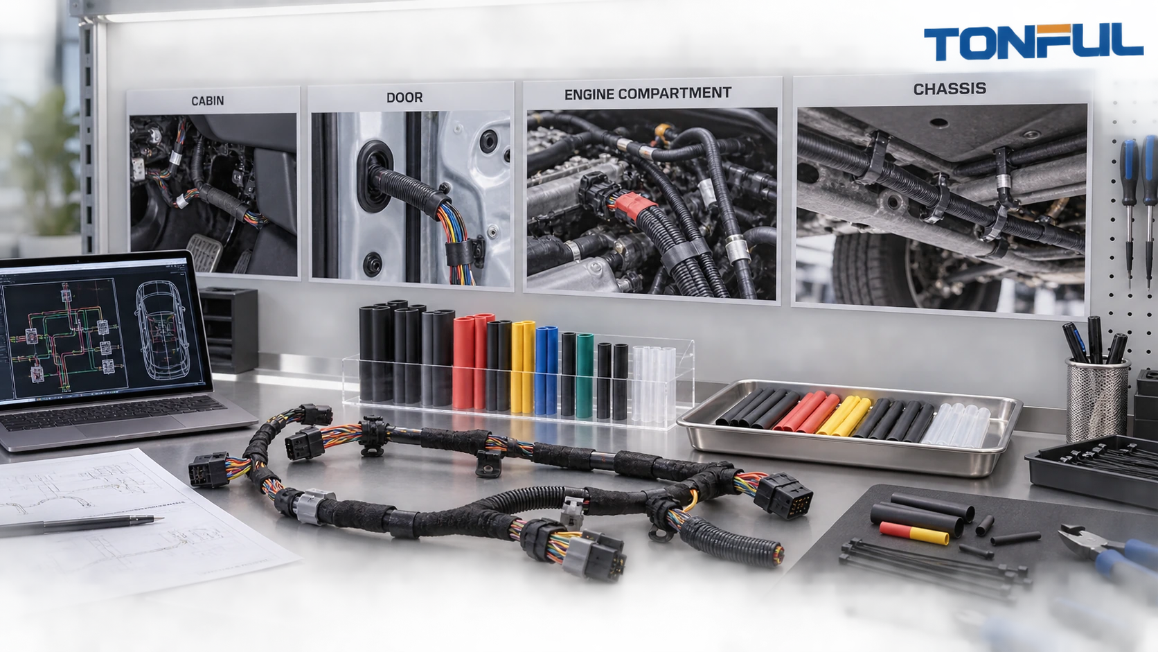
Vehicle mounting zones create different thermal, fluid, flexing and abrasion demands that must be defined before material selection.
Select Material and Wall Construction
Cross-linked polyolefin is common for insulation, bundling and abrasion protection, but the generic material name does not establish a product’s temperature, fluid or flame performance. Elastomeric or fluoroelastomer constructions may be considered for demanding flexibility, temperature or fluid conditions, while fluoropolymers may address thin-wall, chemical or high-temperature needs. The exact product evidence governs.
Use the heat shrink material guide to compare material families. For every candidate, review supplied and recovered dimensions, wall, shrink ratio, recovery conditions, longitudinal change, flexibility, color, printability and product-specific test evidence.
Single-Wall or Adhesive-Lined
Single-wall tubing is useful when the main functions are insulation, identification, bundling, strain transition or abrasion protection and an internal seal is not required. Adhesive-lined tubing adds a thermoplastic liner that can wet compatible surfaces and fill some gaps during recovery. It does not automatically make every splice waterproof.
Multi-wire branches create valleys that a cylindrical sleeve may not seal. Connector backshells may include vents, latch features or irregular geometry. Define substrate compatibility, overlap, liner volume, heat process and leakage or ingress validation. The adhesive-lined tubing guide covers those controls.
TE Connectivity’s official automotive heat shrink overview illustrates that automotive tubing selections differ by mechanical, chemical and sealing purpose and that adhesive compatibility is tied to specific tubing compounds. It is an external product-family example, not proof of a TONFUL rating.
Define Temperature and Fluid Exposure
Build a temperature profile rather than requesting one “temperature rating.” Record normal operating temperature, short-term peaks, cold start or storage, duration, duty cycle, proximity to heat sources and whether the tube is constrained. Installation temperature is a separate requirement: the heat needed for recovery must not damage wire insulation, seals, terminals or connectors.
Thermal aging can change tensile behavior, flexibility, color, adhesive condition and dielectric performance. Define initial and aged measurements, sample allocation and acceptance source. If the tube is installed over a crimp, test the completed joint after relevant conditioning rather than assuming material data protects the electrical interface.
Create a Real Fluid List
Potential exposures can include engine oil, transmission fluid, fuels, coolant, brake fluid, washer fluid, battery-related chemicals, road salts, water, cleaning products and manufacturing fluids. Not every location sees every fluid. Record concentration, temperature, duration, immersion or splash mode, drying and post-exposure checks from the project requirement.
Do not transfer a pass from one fluid to another, or from room-temperature immersion to hot cyclic exposure. Review volume/mass change, swelling, cracking, softening, discoloration, adhesion, dimensions and required electrical/mechanical properties. A tube can look acceptable while losing a critical property.
Control Abrasion, Bending and Strain
Identify contact points with brackets, clips, conduit, sheet metal and neighboring harness branches. Determine whether motion comes from engine vibration, door cycling, steering, seat movement, body flex or service handling. Heat shrink can provide local protection, but it must not replace missing routing clearance, edge protection or strain relief.
Place sleeve ends away from peak bending when possible. A stiff recovered edge can move strain into the adjacent wire. Confirm minimum bend behavior for the finished assembly and support the harness according to the drawing. Inspect for fretting, flattening, splitting, liner pumping and conductor damage after dynamic testing.
Abrasion evidence must describe counterface, load, motion, speed, cycle count, temperature and endpoint. A generic “abrasion resistant” claim cannot be compared without test conditions. For a production harness, include clip position and realistic tension because routing changes contact pressure.

Harness validation should examine the complete routing, including sleeve edges, clips, bend zones and nearby abrasion surfaces.
Validate Sealing as an Assembly
Define what must be sealed: conductor splice, insulation transition, connector rear, cable breakout or another interface. State the water, pressure, immersion, spray, thermal-cycle or leakage test required by the customer. Do not convert visible adhesive flow into an IP claim.
Prepare samples with production wire, terminal, crimp, connector, seal, liner, tube and heating process. Control wire insulation supplier and surface condition because liner adhesion may change with compound, texture, contamination and aging. Include minimum and maximum geometry tolerances.
Inspect both ends and internal paths where appropriate. Section development samples if necessary, but do not present a conceptual cross-section as acceptance evidence. Record sample ID, materials, overlap, heat source, temperature or setting, exposure, observations and result. Approval covers only the tested construction and process.
The single-wall versus dual-wall guide helps determine whether sealing belongs in the design.
Design a Repeatable Installation Process
Specify cut length, placement, overlap and orientation. Define the heat source, nozzle or reflector, distance, motion, fixture and completion indicators. Production controls may use a validated setting window, but an uncontrolled heat-gun dial is not a transferable process specification.
Heat progressively to avoid trapped air and local scorching. Protect temperature-sensitive connector bodies, seals and wire insulation. For lined tubing, confirm adequate flow without pushing excessive liner into a connector or leaving unsupported voids. Allow the assembly to cool before bending or loading it.
Train and authorize operators. Use first-piece verification after setup, tool/nozzle change, material change and restart when required by the control plan. Inspect wrinkles, splits, scorching, incomplete recovery, exposed conductive parts, incorrect position and liner condition. A cosmetic standard should distinguish appearance from functional defects.
Build a Harness Validation Plan
ISO 16750 provides environmental frameworks for electrical and electronic vehicle equipment. ISO 16750-2:2023 addresses electrical loads and explicitly does not cover EMC. ISO 16750-3:2023 and ISO 16750-4:2023 address mechanical and climatic loads. Applicability, severity and acceptance criteria must be defined by the OEM/customer and mounting location; citing these standards does not prove tubing or harness compliance.
If the assembly includes electronics, shielding or communication interfaces, define separate customer-approved EMC/ESD requirements. Material or component testing alone does not establish completed-vehicle EMC compliance.
Sample Allocation and Sequence
State sample quantity, variants and whether tests use independent samples or a defined sequence. Keep unaged references where change is measured. Reserve samples for destructive analysis. Define invalid-test, replacement-sample and retest rules before execution. A valid failure cannot be erased by testing a more convenient specimen.
| Validation area | Controlled inputs | Results to retain |
|---|---|---|
| Dimensional recovery | Product, size, heat process and substrate tolerances | Supplied/recovered dimensions, wall and longitudinal change |
| Thermal exposure | Location profile, duration and sequence | Appearance, dimensions and required property changes |
| Fluid exposure | Exact fluid, concentration, temperature and mode | Change, defects and post-exposure performance |
| Vibration/flexing | Harness route, clips, bend and input profile | Wear location, continuity and visual evidence |
| Abrasion | Counterface, load, motion and endpoint | Damage progression and acceptance decision |
| Sealing | Production assembly, exposure and leak method | Raw observations and pass/fail source |
| Electrical insulation | Electrode/assembly setup and condition | Withstand/breakdown result and method |
The heat shrink testing guide explains laboratory record requirements. Maintain raw data, calibrated equipment IDs, actual conditions, photos, failures, deviations and approvals.

The validation matrix ties every environmental exposure to controlled inputs, retained evidence and a project-specific acceptance source.
Release and Production Control
Approve the exact tube, size, color, material, liner, wire/connector substrates, site and installation process. Define incoming identity and dimensional checks, lot traceability, retention samples, first-piece rules and reaction plans. Monitor assembly defects and field returns by product and lot rather than relying only on supplier certificates.
Supplier changes to resin, pigment, liner, dimensions, extrusion, cross-linking, expansion, site or test method can affect validated performance. Define notification and requalification rules. The bulk heat shrink sourcing guide covers packaging, lots and ongoing supply controls.
Work With TONFUL
Send TONFUL the harness drawing, mounting location, substrates, fit dimensions, environmental profile, required standards, installation process, annual volume and validation plan. TONFUL can discuss available automotive heat shrink tubing options and production-intent samples. Final ratings, certifications and approval scope must be confirmed for the exact quoted product and customer requirements.
—
