
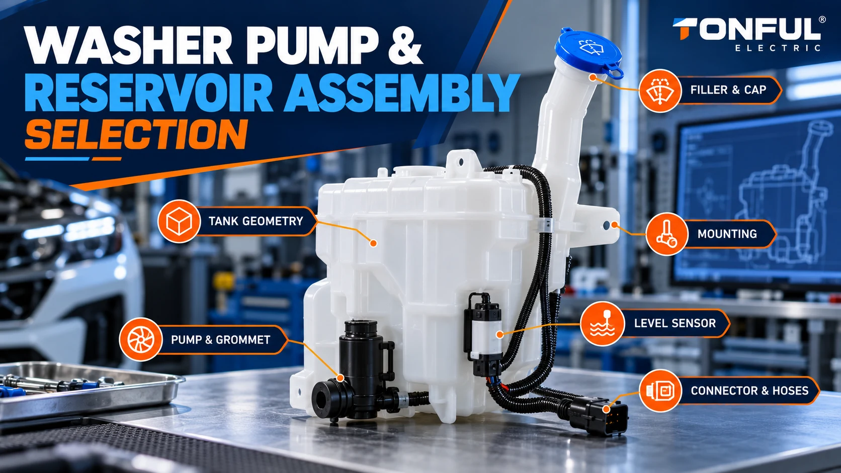
A washer pump and reservoir assembly is more than a pump attached to a plastic tank. The service unit may include one or more pumps, grommets, filters, a level sensor, filler neck, cap, vent, brackets, hoses, valves and wiring interfaces. Two assemblies can use a similar pump yet differ in tank shape, mounting points, body clearance, fluid capacity, outlet routing or sensor logic.
Select the assembly from the complete vehicle and module definition. A pump OE number alone does not prove that the reservoir fits, and a reservoir photograph does not prove that the installed pump has the correct voltage, connector or hydraulic circuit. This guide provides a controlled method for comparing a removed assembly, supplier sample and production-intent part.
On this page: Scope | Architecture | Fitment | Pump interfaces | Tank functions | Validation
Define the Service Scope First
Determine what the buyer is ordering. The same catalog may list a bare pump, pump-and-grommet kit, reservoir without pumps, reservoir with one pump, multi-pump reservoir module or a complete service kit with cap, sensor and hose pieces. Record included and excluded components explicitly.
| Supply Scope | Typical Included Items | Main Approval Risk |
|---|---|---|
| Pump only | Motor/pump body and electrical connector | Existing tank, grommet and hoses may not match |
| Pump kit | Pump, grommet/filter and sometimes connector adapter | Kit content and installation direction can vary |
| Reservoir only | Tank, filler neck, mounting features and ports | Pump holes, seals, cap and sensor may be excluded |
| Pump-reservoir module | Tank plus defined pumps, seals and selected accessories | Vehicle mounting, circuit routing and electrical variants must all match |
| Complete service assembly | Module, cap, sensor, hoses, brackets or hardware as specified | Packaging and catalog text may omit a critical accessory |
TONFUL’s automotive washer pump range establishes the pump product-family context. The exact reservoir-module scope, included parts and vehicle application still require controlled evidence and an approved sample.
Start with the complete service or assembly number when available, then classify every number found on the tank, pump, sensor, cap and bracket. A molded tank number may identify only the shell or mold. It should not automatically replace the complete module service number.

Conceptual illustration only. Confirm the exact kit content and excluded components before quotation or installation.
Map the Complete Assembly Architecture
Create a component map before comparing candidates. Include:
- Reservoir body and molded chambers
- Filler neck, extension tube and cap
- Vent path and overflow boundary
- Pump openings, grommets, filters or strainers
- Front, rear, headlamp or sensor-cleaning pumps
- Fluid-level sensor and its seal
- Check valves, hose fittings and retained hose sections
- Mounting tabs, brackets, bushings and fasteners
- Electrical connectors, clips and harness routing
- Heat shields, splash shields or protective covers if part of the service unit
Use a photograph set with consistent orientation: vehicle-facing view, outboard/inboard sides, top, bottom, filler neck, every mounting point, each pump port and all labels. Mark which components belong to the reservoir supplier and which remain vehicle-level parts.
If multiple pumps are installed, identify each circuit independently. A front windshield pump, rear-window pump and headlamp washer pump can differ in construction, electrical load and outlet. Do not assume pumps are interchangeable because they enter identical-looking tank ports.
Verify Tank Geometry and Vehicle Mounting
Reservoir fit is three-dimensional. Compare overall envelope, molded contours, wheel-arch or body-panel clearance, filler-neck angle and length, cap access, pump orientation and hose space. Record each mounting tab, slot, bushing, bracket and fastener interface against the vehicle drawing or removed part.
A sample can align at one fastener yet interfere with a body panel or harness elsewhere. Install the assembly without forcing the tank, bending brackets or loading the filler neck. Confirm clearance through the vehicle’s applicable movement and service conditions, including hood closure, liner installation, cab movement or adjacent component replacement where relevant.
| Fitment Field | Removed Assembly | Candidate Sample | Evidence and Result |
|---|---|---|---|
| Overall envelope | Record controlled dimensions | Record controlled dimensions | Drawing and installed clearance |
| Mounting points | Quantity, location and interface | Compare every point | Vehicle installation record |
| Filler neck/cap | Position, angle and access | Compare installed position | Fill and service check |
| Pump orientation | Port locations and service clearance | Compare with hoses connected | Installed photographs |
| Sensor position | Location, orientation and connector access | Compare with vehicle harness | Functional check |
| Shields/brackets | Included/excluded and attachment | Confirm supply scope | BOM and packaging record |
Do not invent a universal reservoir capacity tolerance. Capacity, fill level and usable volume must come from the customer drawing, vehicle information or approved specification.

Conceptual illustration only—not a vehicle-specific dimensional drawing.
Verify Every Pump Port, Grommet and Connector
For each tank opening, record diameter/profile, wall or boss geometry, insertion depth, orientation and retained component. Compare the grommet outer and inner interface, lip shape, material specification and filter/strainer boundary. A pump may insert into the hole but leak, tilt, loosen or sit at the wrong depth if the grommet and tank boss are not matched.
Inspect whether the pump inlet reaches the intended low point without contacting the tank. Confirm that molding flash, sink, ovality or weld-line risk at the port is controlled. The installation method should define lubrication or fluid wetting, insertion direction, permissible tool contact and visual confirmation of full seating.
Connector approval requires shell/keying, cavity count, populated terminals, terminal assignment, polarity, mating lock and harness clearance. TONFUL’s automotive electrical connectors page can support connector-family discussions, but it does not establish the module’s exact pinout or sealing. Where a replacement pigtail is supplied, control the custom wire harness assembly separately, including wire, crimp, splice, seal, strain relief and routing.
For each pump, define the nominal vehicle system and voltage measured at the pump under the specified hydraulic condition. Identify polarity reversal, relay/module control, protection and diagnostic behavior. Do not energize unidentified terminals from the nominal vehicle supply.
Check Filler, Vent, Sensor and Fluid Boundaries
Filler Neck and Cap
Verify cap retention, seal, symbols, tether if applicable, filler access and compatibility with the vehicle opening. Confirm that the neck does not kink, crack or transmit installation stress into the tank. A cap that fits by diameter may still have the wrong vent, seal or retention design.
Vent and Overflow
The reservoir must admit air as fluid leaves while controlling splash and leakage according to the vehicle design. Identify whether venting occurs through the cap, a dedicated path or another feature. Do not seal an intended vent or create an uncontrolled leak path. Test fill, operation, vehicle orientation and specified dynamic conditions using the approved plan.
Fluid-Level Sensor
Record sensor type, connector, orientation, switching or output behavior, seal and float clearance. A physically matching sensor may have different polarity, threshold, resistance or module interpretation. Verify the instrument-cluster or body-module response in the intended vehicle, including open/short diagnostic behavior when specified.
Fluid and Material Compatibility
List the approved washer fluids, antifreeze concentration, temperature range, cleaners and nearby service chemicals. Validate tank resin, grommets, seals, cap, sensor and hoses after applicable exposure. Material name alone does not prove compatibility; color, additives, grade, processing and stress state can influence performance.
ISO 16750-4:2023 addresses climatic loads for applicable road-vehicle electrical and electronic equipment. It does not certify a washer reservoir, define universal fluid compatibility or provide a complete tank validation plan. Project documents must define applicable conditioning and acceptance criteria.
Validate Hydraulic Function at Assembly Level
Test the module with the correct reservoir level, fluid or approved surrogate, temperature, pump supply measured under load, hose/nozzle restriction and vehicle-representative orientation. Record priming, flow and relevant pressure points, leakage, current, noise and routing for every circuit.
The reservoir can influence pump performance through inlet submergence, internal shape, trapped air, contamination, filter restriction or port position. A pump that passes on a laboratory supply cup may behave differently in the production tank. Test low-fluid conditions and warning behavior only where the approved specification defines them; do not run a pump dry merely to create a generic demonstration.
Check leakage at the tank seam, molded features, cap, neck, sensor seal, pump grommets and hose connections. Separate immediate assembly leakage from leakage after mechanical, climatic, chemical or endurance conditioning. Preserve failed parts and document whether the primary cause is tank, seal, pump, installation or fixture.

Conceptual illustration only. The approved project plan controls samples, conditioning, limits and failure criteria.
Environmental, Mechanical and Transport Evidence
ISO 16750-3:2023 can frame applicable mechanical-load discussions for road-vehicle equipment. It does not provide one universal vibration or shock profile for every reservoir mounting location. Define orientation, fill state, installed supports, hose/harness mass, operating state and inspection points.
Validate thermal expansion, cold handling, vibration, vehicle motion, mounting fatigue and specified ingress or splash conditions. Review how a full or partially filled tank loads brackets and molded bosses. If the assembly is shipped with pumps installed, packaging must protect filler necks, ports, tabs, connectors and sensor features from compression or impact.
Transport packaging should identify part/revision, included components, lot, quantity and handling orientation. Use separators or supports that do not deform the tank. Receiving inspection must detect missing caps, seals, pumps or brackets and prevent mixing similar reservoir variants.
Build an Assembly-Level Validation Record
| Record Field | Required Entry |
|---|---|
| Identity | Complete assembly number, revision, sample ID, tank and component labels |
| Supply scope | Included/excluded pumps, seals, cap, sensor, hoses, brackets and hardware |
| Vehicle scope | Make/model/market, production or VIN context and installation position |
| Geometry | Envelope, mounting, filler, clearance and service access results |
| Port/interface matrix | Every pump/sensor opening, grommet, connector and hose connection |
| Electrical results | Supply at component, current, polarity, commands, warnings and diagnostics |
| Hydraulic results | Fluid, level, restriction, flow/pressure context, priming and routing |
| Leakage | Seam, cap, neck, sensor, grommet and hose results before/after conditioning |
| Environmental/mechanical | Sample allocation, sequence, conditions, monitoring and final inspection |
| Release | Deviations, acceptance source, approved scope, reviewer and date |
Sample approval applies only to named samples and tests. Production approval must identify the factory, tank and pump revisions, tooling, component sources, assembly process, test coverage and packaging. Changes to resin, mold, grommet, pump, sensor, cap, bracket or supplier require the agreed notification and revalidation decision.
The TONFUL blade fuse range and auto combination switch range are adjacent system references only. Their approval does not prove that the complete pump-reservoir module fits or functions in a particular vehicle.
Work With TONFUL
Send TONFUL the complete assembly reference, vehicle context, removed-module photographs, tank envelope and mounting data, filler/cap details, every pump/sensor port, connector end views and required kit content. TONFUL can organize the pump and interface discussion while keeping reservoir-module approval tied to controlled drawings, production-intent samples and installed-vehicle evidence.