
Moving a custom wire harness from an initial drawing to repeatable production is not a single quotation event. It is a controlled sequence of requirement review, conflict resolution, design-for-manufacture decisions, component approval, sample construction, validation, release and change management. Skipping one stage can leave ambiguity hidden until equipment installation or a repeat order.
The project below is an anonymized composite built from common cable-assembly workflow patterns. It is not a claim about a named customer, actual order, measured yield, lead time or TONFUL production result. No quantities, ratings, test limits or performance values should be copied into another project. Its purpose is to show what evidence an OEM buyer and manufacturer should create together.
Project Starting Point: A Functional Drawing, Not a Production Package
The hypothetical buyer supplied an equipment interconnect drawing for a compact control unit. The assembly included a board pigtail, two sensor branches, a motor branch, protective sleeving and labels. The drawing showed connectivity and approximate routing, but several production fields were unresolved:
- Connector family names without full housing and terminal part numbers.
- One connector shown from an unspecified viewing direction.
- Wire colors listed without controlled wire specifications.
- Branch lengths without named measurement datums.
- Sleeve and label locations shown pictorially but not dimensioned.
- Continuity required, but no fixture map or acceptance document.
- An environment description without local temperature or flex zones.
These gaps did not mean the design was poor. They meant the document was at a functional-design stage. The first manufacturing task was to convert assumptions into controlled decisions using the questions in the custom wire harness buying guide.
Gate 1: Create a Requirement and Conflict Register
The manufacturer should not silently choose the easiest interpretation. Each ambiguity becomes a numbered question with source, owner, risk, proposed resolution, approval and date. The project remains on hold for any conflict that can change fit, polarity, safety, performance or regulatory scope.
| ID | Open requirement | Risk | Evidence needed | Decision owner | Status |
|---|---|---|---|---|---|
| Q-01 | Connector end-view direction | Mirrored cavity map | Supplier drawing and board schematic | Customer engineering | Open/closed |
| Q-02 | Terminal and wire combination | Uncontrolled crimp | Component and wire specifications | Joint review | Open/closed |
| Q-03 | Branch-length datums | Installation mismatch | Equipment routing model | Customer mechanical | Open/closed |
| Q-04 | Test acceptance limits | False pass/fail | Customer test specification | Customer quality | Open/closed |
| Q-05 | Sleeve and label position | Assembly interference | Installed-sample review | Customer engineering | Open/closed |
The wire harness drawing and pinout guide gives a disciplined method for reconciling connector drawings, schematics, BOMs and board references. Only the customer or authorized design owner can approve a change to intended circuit behavior.
Gate 2: Convert the BOM Into Controlled Components
Every line in the preliminary BOM was expanded into manufacturer, full part number, description, revision/status, approved source and substitution rule. Connector entries included housing, terminal, seal, cavity plug, secondary lock and mating reference where applicable. Wire entries included construction, conductor size, insulation, color and approved source.
The review separated three categories:
- Customer-specified component: no substitution without written approval.
- Performance-defined component: manufacturer may propose an exact part, subject to evidence and approval.
- Process consumable: controlled by the manufacturer’s qualified process unless contractually specified.
This prevented a common mistake: approving a housing while leaving terminals and tooling undefined. The connector selection process treats the entire termination system as the approval unit.
No component was described as certified, equivalent or approved without evidence for that exact part and application. Availability was reviewed separately from technical suitability; a readily available substitute could not bypass mating and validation checks.
Gate 3: Run a Focused DFM Review
The DFM review used the equipment routing path rather than only the flat drawing. Manufacturing and customer teams examined branch breakout locations, service loops, bend direction, connector mating access, clip positions, abrasion points, heat zones and installation sequence. They also checked whether tooling could reach each termination and whether inspection features would remain visible.

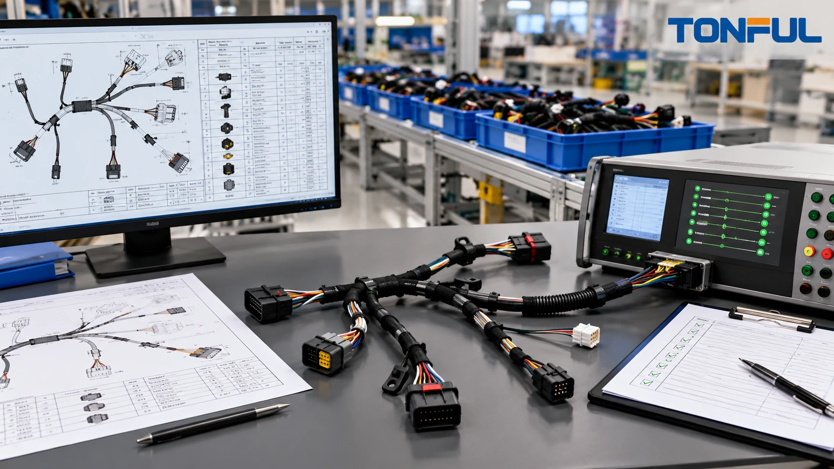
Conceptual DFM review illustrating the evidence exchanged between equipment design and harness manufacturing; it is not a customer drawing.
Proposed changes were recorded as requests, not silently added to the drawing. Examples included moving a breakout away from a sharp enclosure edge, adding free length before a tight turn and clarifying a sleeve endpoint. The detailed wire harness DFM checklist supplied the review structure.
DFM did not authorize the manufacturer to change circuit function, wire rating or connector family. It identified manufacturability and installation risks for the design owner to resolve.
Gate 4: Freeze the Production-Intent Document Set
After questions were resolved, the release candidate package contained:
- Assembly drawing with revision and effective date.
- Complete BOM with controlled component identities.
- Connector end views and cavity-to-circuit table.
- Wire schedule, splice schedule and branch dimensions.
- Covering, labels and packaging instructions.
- Workmanship/acceptance-source document and class where contractually applicable.
- Qualification, first-article and production-test plans.
- Approved deviations and open-item disposition.
IPC states that IPC/WHMA-A-620E describes materials, methods, tests and acceptability criteria for cable and harness assemblies. In a real project, the contract must identify the applicable document, revision, class and any customer additions. The standard does not replace the product drawing or define project-specific test frequency by itself.
The released package received a baseline identifier so sample evidence could be traced to exactly what was built. Later redlines could not overwrite that baseline.
Gate 5: Plan the Manufacturing Process Before Building Samples
The manufacturer converted the design into a process flow: incoming verification, wire cutting, stripping, crimping, terminal insertion, branch forming, covering, labeling, dimensional inspection, electrical test and final release. Each step linked to a work instruction, equipment/tooling, inspection method and reaction plan.
Potential high-risk points included connector orientation, terminal insertion, branch datum, splice position and label identity. Fixtures or poka-yoke were considered where an error could be difficult to detect later. Test adapters were keyed and labeled to avoid mirroring the same drawing error they were intended to catch.
Process preparation also included training/authorization, calibration status, tooling maintenance, material segregation and lot-record design. A sample built by special hand methods that cannot be repeated in production provides weak release evidence, so production-intent tools and instructions were used wherever feasible.
Gate 6: Build and Inspect First-Article Samples
Each sample received a unique ID linked to material lots, drawing revision, operator/equipment and test results. Sample quantity and allocation came from the approved plan: some samples could support dimensional and electrical checks, while destructive pull or section analysis required separately identified units.
The first-article review followed the wire harness first-article inspection checklist:
- Document and BOM verification.
- Connector, terminal, wire and covering identities.
- Cavity map and terminal seating.
- Branch lengths and component positions from named datums.
- Crimp/process evidence from approved acceptance sources.
- Labels, orientation, workmanship and packaging.
- Complete electrical net-list result.
- Installed-equipment fit and mating review.

Conceptual first-article record; project documents define the actual sample count, measurements and acceptance criteria.
An installed sample revealed whether routing, service loops, connector access and protection worked in the real enclosure. A bench-level continuity pass alone could not provide that evidence.
Gate 7: Execute Validation Without Inventing Universal Limits
The approved plan separated product-specific qualification from routine production testing. Continuity and short/open tests verified the circuit map. Conditional resistance, pull, environmental, flex or dielectric tests were included only when required by the drawing, customer specification or applicable standard.
Every test record identified sample ID, preconditioning, equipment, calibration status, fixture, method, raw result, limit source, pass/fail and reviewer. Destructive tests preserved failure mode. Fixture-caused invalid tests followed predefined rules; a failed sample was not automatically replaced until root cause and authorization were documented.
If a value was missing, the team returned to the design owner. It did not copy a limit from another harness. This maintained the boundary between manufacturing evidence and engineering authority.
Gate 8: Close Deviations Before Production Release
Sample findings were classified as document error, material issue, process issue, fixture issue, installation conflict or customer-requested change. Each corrective action had an owner, due date, evidence and closure approval. A redline became a released revision before production rather than remaining as an operator note.
The release checklist required:
| Release item | Required evidence |
|---|---|
| Design baseline | Approved drawing, BOM and pinout revision |
| Components | Approved sources and substitution rules |
| Process | Flow, work instructions and qualified tooling |
| Inspection | Characteristics, method, frequency and reaction plan |
| Test | Program revision, fixture map, limits and stored results |
| Samples | First-article/validation disposition and installed review |
| Deviations | Closed or formally time/quantity-limited |
| Traceability | Lot genealogy and record-retention fields |
| Packaging | Approved pack and label configuration |
| Authorization | Product, site, process, revision and approver scope |
A conditional release, when contractually permitted, should define exact product, quantity or period, deviation, owner and expiry. It must not be presented as unrestricted approval.
Gate 9: Preserve the Approved State in Repeat Production
Production release began control rather than ending it. Each lot linked finished assemblies to drawing/BOM revision, component lots, process/tooling identity, inspection and electrical-test records. The revision-control and lot-traceability guide provides the genealogy structure.
Changes to connector, terminal, wire, covering, splice, supplier, tooling, software/test program, fixture, factory or process required review before implementation. The change record identified reason, affected inventory, validation impact, effective lot and customer approval where required.
Repeat orders used the released package, not memory or an old sample alone. When a component became unavailable, procurement raised a controlled change request rather than purchasing a visually similar alternative.
A Reusable Project Record

A gate-based project record keeps decisions and evidence visible from initial requirements through controlled repeat production.
| Gate | Entry evidence | Exit evidence | Owner/approver |
|---|---|---|---|
| Requirement review | Customer inputs | Closed conflict register | Enter |
| Component control | Preliminary BOM | Approved component matrix | Enter |
| DFM | Routing and assembly model | Approved DFM actions | Enter |
| Document freeze | Resolved requirements | Released baseline | Enter |
| Process planning | Released design | Flow/instructions/tooling | Enter |
| First article | Production-intent samples | Inspection disposition | Enter |
| Validation | Approved test plan | Reviewed test evidence | Enter |
| Production release | Closed findings | Scoped authorization | Enter |
| Change control | Proposed change | Approved effective revision | Enter |
What Buyers Should Send With a New Project
To start efficiently, provide the controlled drawing and BOM, connector references and end views, wire/cable requirements, equipment routing context, environmental conditions, applicable acceptance documents, test responsibilities, expected sample stage, forecast and change-notification needs. Identify unresolved assumptions rather than hiding them in notes.
TONFUL can review a project-specific harness package for requirement gaps, DFM, component control, sample planning, test coverage and production records. Send the latest controlled files and open questions for a technical and quotation review. Any resulting proposal, sample approval or production release should be limited to the documented configuration and evidence; this anonymized workflow is not proof of a specific customer result.
—