
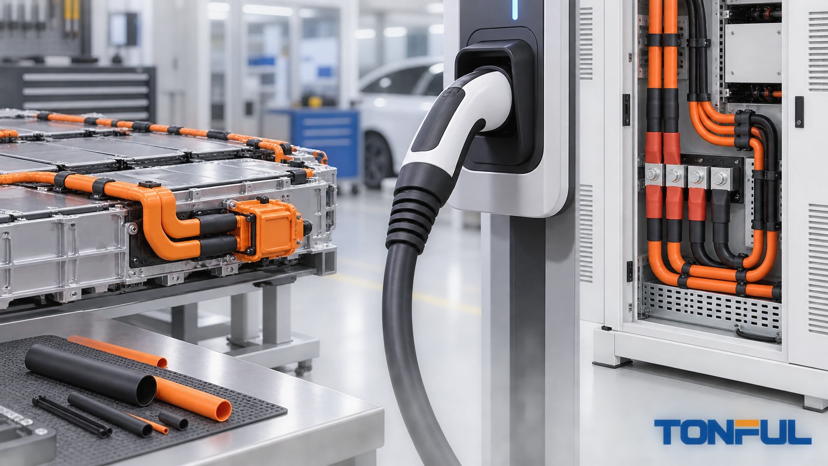
Heat shrink tubing can insulate busbars, protect cable terminations, identify high-voltage circuits and support sealed transitions in electric vehicles, charging equipment and stationary energy storage. These are not one application. Vehicle battery packs face automotive vibration, fluids, packaging constraints and crash-related design requirements. Charging assemblies experience flexing, handling, contaminants and connector heating. Stationary storage combines battery modules with enclosures, power conversion, controls and site-level fire and electrical requirements.
The tubing must therefore be selected for a defined component and verified within the complete system. Color, wall thickness or a generic voltage label cannot establish electrical safety. High-energy equipment should be designed, assembled and serviced by qualified personnel under the applicable isolation, lockout, discharge, verification and personal-protection procedures.
Classify the Application Before Selecting Material
Start by naming the system, location and function. “EV-grade heat shrink” is not a complete specification.
| Application | Possible heat-shrink role | System evidence that remains necessary |
|---|---|---|
| Battery module or pack | Busbar insulation, terminal cover, cable transition, identification | Creepage/clearance, pack dielectric design, thermal and abuse validation |
| Vehicle high-voltage harness | Splice/termination protection, abrasion, identification | Cable, connector, routing, crash and vehicle electrical safety evidence |
| On-board charger/inverter | Component lead insulation and internal cable protection | Equipment insulation coordination, thermal and EMC design |
| EV charging cable/connector | Termination boot, repair prevention, identification | Cable flex, connector temperature rise, ingress and complete assembly tests |
| Stationary battery rack | Busbar/cable insulation and marker sleeves | Rack/enclosure protection, controls, spacing and installation requirements |
| Containerized ESS | Local wire protection inside certified equipment | Complete ESS safety, fire propagation and site approval |
Do not use field-applied tubing to conceal damage in a high-voltage cable, charging connector or battery interconnect unless the equipment manufacturer has an approved repair procedure. A visually covered defect may retain electrical, thermal or mechanical hazards.
Define the Electrical Function
Specify whether the tubing is basic insulation, supplementary protection, a barrier against incidental contact, abrasion protection, environmental sealing or identification. These functions have different acceptance criteria. Tubing should not be assigned the complete system’s insulation function without an engineering analysis.
Record nominal and maximum working voltage, transient conditions, circuit category, pollution/contamination environment, spacing design, conductor geometry, grounded structures and fault response. Dielectric strength from a material datasheet is a test result under stated conditions, not a universal operating-voltage rating for any installed sleeve.
ISO 6469-3:2021 addresses electrical safety requirements for voltage-class-B propulsion circuits and conductively connected auxiliary circuits in electrically propelled road vehicles, including protection against electric shock and thermal incidents. The official ISO 6469-3 page defines that system scope. It does not certify a piece of tubing or provide a generic sleeve voltage rating.

Vehicle, charging and stationary-storage applications require separate system requirements and approval evidence.
Map Temperature From Source to Sleeve
Identify steady-state and transient heat sources: cells, busbars, contactors, fuses, terminals, power electronics, charging contacts and adjacent cooling components. Include ambient extremes, current duty, enclosure conditions, thermal management faults and heat generated by a resistive connection.
The tubing’s service-temperature range, shrink process and thermal aging all matter. A high recovery temperature can damage cell seals, connector plastics, cable insulation, adhesives, sensors or nearby electronics even if the recovered sleeve later tolerates service temperature. The high-temperature automotive heat shrink guide explains why installation temperature must be separated from operating exposure.
Measure temperature at the proposed location during representative operation. Do not assume pack air temperature equals busbar or terminal temperature. Validate the complete stack of conductor, plating, joint, insulation, sleeve and enclosure because heat can alter contact pressure and polymer properties.
Select Material by Exposure, Not Color
Orange is commonly associated with vehicle high-voltage wiring, but color alone does not prove voltage class, material, flame behavior, fluid resistance or compliance. Define color using the customer’s controlled requirement and verify aging and lot consistency where identification is safety-relevant.
Consider:
- operating and storage temperatures;
- electrolyte, coolant, oil, grease and cleaning chemicals;
- humidity, condensation, salt and water exposure;
- abrasion against busbars, edges, clamps and enclosures;
- UV and weathering for outdoor charging or storage equipment;
- flame, smoke and halogen requirements applicable to the equipment;
- flexibility or stiffness after recovery;
- adhesive compatibility with cable jackets, metals and coatings;
- shelf life and storage for adhesive-lined constructions.
The polyolefin versus PVC heat shrink comparison illustrates why polymer family is only the beginning of selection. Formulation, crosslinking, wall, additives and test evidence determine performance. Do not substitute a material based solely on the same generic polymer name.
Design Busbar and Battery-Terminal Coverage
Busbars may have rectangular sections, bends, holes, fasteners and abrupt transitions. Round-tube sizing shortcuts can leave thin corners, trapped air or exposed edges. Measure width, thickness, corner radius, fastener envelope and the largest pass-over feature. Define which surfaces remain intentionally bare for mating, sensing or grounding.
Use a controlled cut and recovery process so sleeve ends do not enter contact interfaces. At bolted joints, tubing should not be trapped where it changes clamp load unless the design explicitly permits it. Protect sharp edges and validate corner wall distribution after recovery.
The busbar heat shrink tubing guide provides a detailed geometry and insulation-coordination workflow. In a battery pack, integrate that design with cell spacing, cooling, service disconnects, sensing and enclosure clearances.

Conceptual illustration only—not an electrical-clearance or acceptance standard. Coverage and exclusion zones must come from the approved pack design.
Protect Cable Terminations Without Hiding Defects
At lugs, splices and connector backshells, confirm the electrical joint before covering it. Heat shrink can provide insulation and transition protection but cannot correct poor crimp geometry, loose fasteners, damaged strands or terminal overheating.
Size from the largest lug, barrel or backshell feature and the smallest cable jacket. The heat shrink tubing sizing guide explains supplied and recovered diameter checks. Record overlap, longitudinal change and available straight cable length. Keep the sleeve edge away from the primary flex zone and use clamps or backshells to carry harness loads.
For adhesive-lined tubing, verify jacket and metal compatibility, surface preparation, sealant flow and cooling. An edge bead does not prove the internal interface is void-free. High-voltage cable shields, screens and grounding paths require their own controlled termination; tubing must not interrupt or conceal an incomplete shield connection.
Treat Charging Cables as Dynamic Assemblies
Charging cables are handled, dropped, coiled, flexed and exposed to contaminants. A rigid repaired area or abrupt sleeve edge can concentrate bending. Do not use generic tubing as a field patch on a damaged EV charging cable unless the manufacturer explicitly authorizes the repair and defines inspection and testing.
IEC 62196-1 covers EV plugs, socket-outlets, vehicle connectors, inlets and applicable cable assemblies for conductive charging systems, including thermal, mechanical and contaminant-related requirements. Consult the current applicable edition and product-specific parts of the series. The official IEC 62196-1 page demonstrates that approval concerns the accessory and cable assembly, not a sleeve in isolation.
For production terminations, validate cable OD, conductor arrangement, shield, jacket, boot or tubing, bend transition, pull/load path and connector temperature behavior together. Confirm identification remains legible after flex and environmental conditioning.

The connector, cable, shield, boot and strain-relief system must be evaluated as a complete charging assembly.
Keep Stationary ESS Requirements at System Level
Stationary storage equipment can include cells, modules, racks, power-conversion equipment, controls, cooling, enclosures and site wiring. Heat shrink may protect a local busbar or wire, but it cannot establish the fire, electrical or control safety of the ESS.
UL Solutions explains that UL 9540 addresses energy storage systems and equipment as a comprehensive system, including charging/discharging, protection, controls, communications and other functions. UL 9540A addresses thermal-runaway fire-propagation evaluation. See the official UL energy storage testing overview. A tubing test or certificate cannot be presented as UL 9540 or UL 9540A system compliance.
Inside an ESS, also evaluate ventilation, hot surfaces, fault energy, service access, wire segregation, condensation, rodents, cleaning and replacement procedures. Any field repair should preserve the listed or approved system configuration and follow manufacturer and authority requirements.
Validate the Production-Intent Assembly
Build the test plan from the application requirement. Define sample quantity and allocation, worst-case sizes, material lots, processing, preconditioning, test sequence, equipment accuracy, acceptance criteria, invalid-test rules and failure analysis.
| Validation area | Conditions to define | Evidence to retain |
|---|---|---|
| Dimensions/recovery | Geometry, heat process and inspection points | Before/after dimensions and images |
| Electrical insulation | Test method, voltage, duration and environment | Raw results and acceptance source |
| Thermal performance | Current/load, ambient, cooling and measurement locations | Temperature traces and configuration |
| Mechanical | Vibration, flex, abrasion or pull conditions | Failure location and post-test inspection |
| Environmental | Fluids, humidity, water, salt or UV as applicable | Exposure details and condition change |
| Fire/material | Applicable equipment requirement and specimen preparation | Exact report and product identity |
| Aging | Thermal/environmental sequence and reference sample | Initial, interim and final comparison |
| System interaction | Connector, busbar, cable, enclosure and controls | Production-intent assembly record |
Do not combine unrelated tests into a claim that the tubing is “EV certified.” State exactly which product, specimen, method, conditions and criteria were evaluated.

Conceptual validation matrix only—not proof of compliance. Test conditions and acceptance criteria must come from the applicable project plan.
Control Production and Changes
Incoming inspection should verify product family, size, color, construction, lot, packaging and required documents. The bulk heat shrink tubing sourcing guide explains lot traceability and change notification. For high-energy systems, link the installed tubing lot and process record to the battery pack, charging assembly or ESS equipment identity where required.
Use first-piece verification after material, size, heat-equipment, recipe, fixture or design changes. Monitor position, recovery, surface condition, wall distribution and seal evidence defined by the control plan. Quarantine mixed or unidentified material.
Changes in pigment, formulation, adhesive, wall, supplier site or process can affect installation and aging. Require review before use, even when the commercial description remains unchanged.
EV and ESS Heat Shrink Specification Record
| Field | Required entry |
|---|---|
| System boundary | Vehicle pack, HV harness, charger, cable assembly or ESS |
| Component/function | Busbar, terminal, cable, marker, barrier or seal |
| Electrical conditions | Working/fault/transient context and insulation role |
| Geometry | Maximum pass-over, recovery surfaces and coverage |
| Material | Polymer, wall, liner, color, lot and drawing |
| Environment | Temperature, fluids, humidity, UV, abrasion and fire requirements |
| Installation | Heat equipment, process window, protection and inspection |
| Validation | Samples, sequence, results and acceptance source |
| Traceability | Material/process linkage to finished equipment |
| Approval | Scope, deviations, reviewer and date |
Work With TONFUL
TONFUL can review heat shrink tubing requirements for defined EV, charging and energy-storage components. Provide the system boundary, electrical function, geometry, material and color requirements, thermal and environmental profile, installation process, applicable standards and validation plan. Candidate products and samples can then be discussed. Voltage suitability, high-voltage identification, flame behavior, environmental sealing and system compliance must be confirmed from product-specific evidence and completed-assembly approval.