
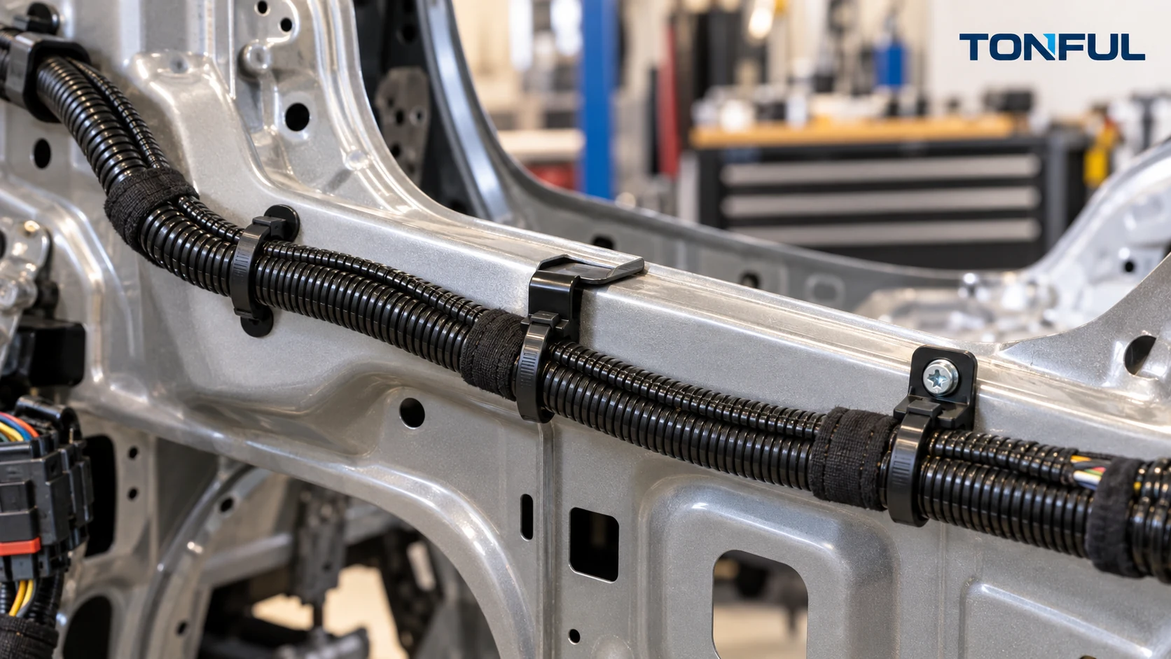
An automotive cable tie can hold a bundle firmly yet still fail as a harness fixing. The strap may remain intact while a fir-tree stem backs out of a hole, an edge clip walks along a flange, or a mounting base loosens under cyclic movement. Selection therefore begins with the vehicle’s attachment point and harness route, not only the tie’s loop tensile number.
This guide compares fir-tree, edge-clip and fastened mounting designs for vehicles and equipment. It identifies required dimensions, vibration evidence and production-intent samples. It does not prescribe a universal pull-force, spacing or vibration limit, or treat a generic stress claim as evidence for a specific fixing.
Define the Installed Harness Function
Mark every attachment point on the controlled harness drawing. Distinguish a location that merely groups wires from one that supports a heavy branch, fixes a connector’s position, protects a sharp edge, or maintains clearance to moving and hot parts. Record the nearest branch, connector, grommet, bend and service disconnect. A fixing that is safe in a horizontal cabin panel may be unsuitable beside a powertrain bracket.
The IEC 62275:2022 description covers cable ties and associated fixing devices for managing or securing wiring systems in electrical installations and notes that additional requirements can apply to other support applications. It is a useful framework for separating tie and fixing-device evidence, but is not an automatic approval of a tie for a particular vehicle location. Vehicle drawings, OEM requirements and the agreed qualification plan define the actual release criteria.
Use a route review to identify temperature, fluids, water, dust, vibration, panel coating and assembly direction. A material name or catalog photograph does not prove finished-part suitability.
Compare Mounting Architectures
| Fixing approach | Attachment interface | Main selection evidence | Typical mismatch |
|---|---|---|---|
| Fir-tree or push-in mount | Defined round, oval, threaded or blind hole | Hole geometry, panel thickness, insertion/extraction, orientation | Similar stem inserted into wrong hole or coating thickness |
| Edge clip | Defined flange edge | Edge thickness, lip shape, coating, installation direction, retention | Clip grips nominal thickness but shifts under harness pull |
| Screw-mounted base | Approved hole and fastener | Base, screw, torque, substrate and service access | Tie passes while fastener loosens or damages panel |
| Weld-stud or dedicated mount | Approved stud or vehicle feature | Stud dimensions, clip engagement and assembly access | Mount fits visually but lacks retention on actual stud |
| Adhesive base | Approved prepared surface | Surface, cleaning, temperature, aging and peel/shear evidence | Uncontrolled surface or heat reduces adhesion |
The HellermannTyton automotive fixing-selection guide illustrates how a hole, edge or stud leads to different fixing designs. Its product-specific claims and dimensions are examples of manufacturer evidence, not specifications for TONFUL products or every vehicle. Ask for the correct drawing and test report for the proposed TONFUL model.
TONFUL Model Confirmation Table
TONFUL’s public cable-tie page does not currently publish a model-level automotive fixing table. The following structure is therefore a controlled data request, not a product claim. Populate it only from a TONFUL drawing, approved sample and applicable test report; do not copy dimensions or ratings from another manufacturer’s catalog.
| TONFUL model | Fixing method | Panel interface | Verified bundle range | Material | Validation status |
|---|---|---|---|---|---|
| To be confirmed | Fir-tree | Hole diameter, panel thickness and coating to be confirmed | To be measured and documented | Grade to be confirmed | Drawing / sample / report pending |
| To be confirmed | Edge clip | Edge thickness, profile and installation direction to be confirmed | To be measured and documented | Polymer and any metal insert to be confirmed | Drawing / sample / report pending |
| To be confirmed | Screw mount | Hole, fastener, torque and substrate to be confirmed | To be measured and documented | Grade to be confirmed | Drawing / sample / report pending |
For each released row, add part revision, mold or cavity traceability where applicable, insertion force, pull-off force, longitudinal slip or retention result, test direction, conditioning, vibration profile, harness mass and acceptance-source document. A blank or pending field is not conformity.

Conceptual illustration only—not an acceptance standard or laboratory micrograph. Dimensions and acceptance criteria must come from the selected parts and vehicle drawing.
Fir-Tree and Push-In Mounts
A fir-tree stem uses flexible ribs to engage a specified hole or panel stack. Some designs include a disc, seal or offset to locate the bundle; those features must be confirmed for the exact model. Specify hole diameter and shape, allowable panel thickness including coating, entry direction, available backside clearance and the required insertion and extraction characteristics. A hole in sheet metal is not interchangeable with a molded boss or a threaded hole without supplier evidence.
During assembly, ensure the stem seats fully rather than resting on a burr, uneven coating or misaligned panel. Confirm any seating cue and the approved removal or hole-reuse method.
The push-mount versus fir-tree automotive guide explores design differences. Do not substitute one stem for another based on appearance or nominal hole size alone; compare tolerances and installed retention after conditioning.
Edge Clips
An edge clip attaches to an existing flange without drilling. That may reduce panel modifications, but the edge has to be a controlled mounting feature. Record flange thickness and tolerance, lip radius, coating or trim, insertion direction, available run length and any stop feature. Evaluate both pull-off force and movement along the edge, since a clip that resists normal extraction may still migrate longitudinally.
The tie or saddle can position the harness parallel or perpendicular to the edge. An offset may protect the insulation from a cut flange; a wrong offset can place it directly against that edge. Test the actual panel and harness mass, not a smooth laboratory coupon alone. If the clip has a metal insert, inspect its contact with paint and corrosion protection. The edge-clip selection guide offers a more focused comparison of interface options.
Screw, Stud and Adhesive Mounts
A screw mount can provide a deliberate attachment where an approved hole and fastener exist. Define screw type, torque, washer or locking feature, base material, panel stack and access for installation and removal. Too much torque can crack a polymer base; too little can permit rotation. Validate the joint as assembled, including whether nearby wires obstruct the tool.
A stud clip depends on the actual stud geometry and coating. Adhesive bases depend on surface preparation, dwell, temperature and aging. Tie strength does not prove base retention, and holes or adhesive must not be added without engineering authorization.
Do Not Confuse Loop Strength With Fixing Retention
The tie loop, locking head, fixing stem, edge grip, panel and cable insulation form a series of potential failure points. A supplier’s minimum loop tensile value typically describes a controlled tie test, not the pull-off of an assembled harness from a vehicle panel. The cable tie tensile strength guide helps distinguish rated tie behavior from installed working loads. Where a fixing device is integral, examine its own test method and declared use.
Map the load direction. Harness weight may pull downward at rest; door closing, road vibration or service handling may pull sideways or twist the mount. A cable branch may create a lever arm that a straight-line extraction test misses. Compare a light signal-wire bundle, a thick corrugated conduit and a connector-heavy branch separately. Include retained slack and support points so that a mount does not transfer force into a connector terminal.
Set a tie-tool tension that secures the bundle without crushing insulation, conduit or shielding. Inspect the flush-cut tail and head position. A wide strap may distribute pressure differently from a narrow one, but the exact installed pressure depends on tool setting and bundle geometry. Define permissible compression, routing clearance and installation work instruction from the harness and vehicle requirements.
Design for Vibration and Vehicle Environment
Vehicle vibration is not a single number. Frequency content, acceleration direction, duration, mounting stiffness and temperature interact. A clip near a cab door, a frame rail and a powertrain mount may see different spectra. The applicable OEM or customer profile should define installation orientation, operating state, harness mass, adjacent clearances and post-test inspection. Do not write a universal claim that any fir-tree or edge clip is vibration-proof.
Use production-intent panels and harnesses for a representative validation fixture. Monitor tie looseness, mount displacement, insulation abrasion, cable-to-panel clearance, connector strain and any new noise. Record the condition before test, during interruptions and after conditioning. A post-vibration extraction result alone may miss progressive movement that occurred earlier. Investigate whether a failure began at the tie, fixing interface, panel edge or an upstream route change.
Temperature and moisture can change polymer behavior; oil, cleaners, road salt and dust may affect materials and interfaces. Verify the chosen material and exact product’s evidence against the location. The cable tie materials guide compares PA66, PA12, ETFE and stainless options, but material-family descriptions do not establish performance for an unverified finished fixing. A metal clip does not remove corrosion, sharp-edge or galvanic-contact concerns. An adhesive mount requires its own temperature and surface-aging review. Where components include electronics or touch a vehicle electrical system, define separate electrical, EMC or ESD requirements as applicable; a mechanical tie standard does not settle those questions.
Build a Production-Intent Verification Plan
Agree sample quantities, lots and test allocation before collecting results. Decide whether environmental and vibration exposures use the same sequential samples or independent groups, whether unaged references are held, which tests are destructive and how invalid tests or replacements are handled. Report failures rather than replacing a sample silently. Acceptance values and statistical confidence must come from the customer drawing, product specification or approved test plan, not a generic blog number.
| Check | Record before testing | Confirm afterward |
|---|---|---|
| Identity | Part number, revision, material, lot and marking | Traceability to tested production-intent item |
| Panel fit | Hole/edge/stud dimensions, coating and tolerances | Seating, damage, migration and repeatability |
| Installation | Tool, setting, operator and insertion direction | Tail, head, bundle pressure and visual acceptance |
| Retention | Test direction, fixture and acceptance source | Initial/aged pull-off, slip and failure mode |
| Environment | Temperature, fluids, moisture and sample sequence | Cracks, embrittlement, corrosion and changes |
| Vibration | Profile source, axes, harness mass and mounting | Movement, abrasion, connector strain and noise |
| Release | Sample IDs, drawing and reviewer | Approved scope, deviations and control plan |
Inspection should cover the panel feature and harness as well as the tie. Where a mount uses a hole, measure the actual hole and coating across representative body lots. Where it clips to an edge, include edge-thickness extremes and realistic assembly angles. Where it screws down, inspect torque and substrate condition. Use the same critical features in production controls and incoming inspection.
The cable tie testing guide explains loop tensile, locking and conditioning records. For automotive mounts, extend that evidence to the complete tie-fixing-panel-harness assembly: include insertion, extraction, longitudinal migration, post-conditioning retention and the first observed failure mode. Do not substitute a loop-tensile result for panel-interface retention.

Installed-condition inspection should identify the first failing interface, not merely whether the strap remains unbroken.
Conceptual illustration only—not an acceptance standard or laboratory micrograph.
Diagnose a Loose or Broken Harness Fixing
Quarantine the affected vehicle or lot as appropriate and preserve the failed hardware, its panel location and a nearby good comparison. Photograph the harness before moving it. Note part/lot, operator and tool, hole or edge dimensions, route change, cable weight, exposure and service history. Check for an over-tight strap, an unseated stem, clip walk, loosened fastener, panel damage and abrasion direction.
Classify whether failure began in the strap, lock, fixing interface, panel, fastener or harness route. A broken tie may be a secondary effect of connector or bundle movement, not the original cause.
Confirm root cause with controlled reassembly and the relevant test, then define containment, permanent corrective action and prevention. Changes to part, panel hole, edge geometry, tension tool or route may require revised drawing, work instruction, control plan and customer approval. Do not enlarge a hole or add a second tie in the field as an undocumented workaround.
Select and Release With TONFUL
TONFUL’s cable tie range can be reviewed against a vehicle-specific application, but the public page does not currently identify automotive fixing SKUs, interface ranges, material grades, insertion or pull-off results, longitudinal retention, vibration profiles or report numbers. Its broad statement about severe mechanical stress and vibration should therefore be read as a general positioning statement, not as product-specific validation.
For publication and quotation use, a safer capability statement is: “Suitability for mechanical stress and vibration depends on the exact fixing model, panel interface, harness mass, installation method, environmental conditioning and customer-approved vibration profile. Confirm the applicable drawing, sample and test evidence before release.” Provide the harness drawing, panel dimensions and tolerances, bundle size and mass, mounting orientation, fluids, temperature, vibration requirement, installation tool and acceptance-source document. Ask for actual sample and drawing evidence, not a generic assertion of automotive suitability.
Approve the combination of tie, mount, panel and route only for the tested vehicle or program scope. Record the approved revision, packaging, lot traceability and change-notification expectations. A later material, mold, clip-insert or panel-coating change can alter retention even if the catalog name stays the same.