
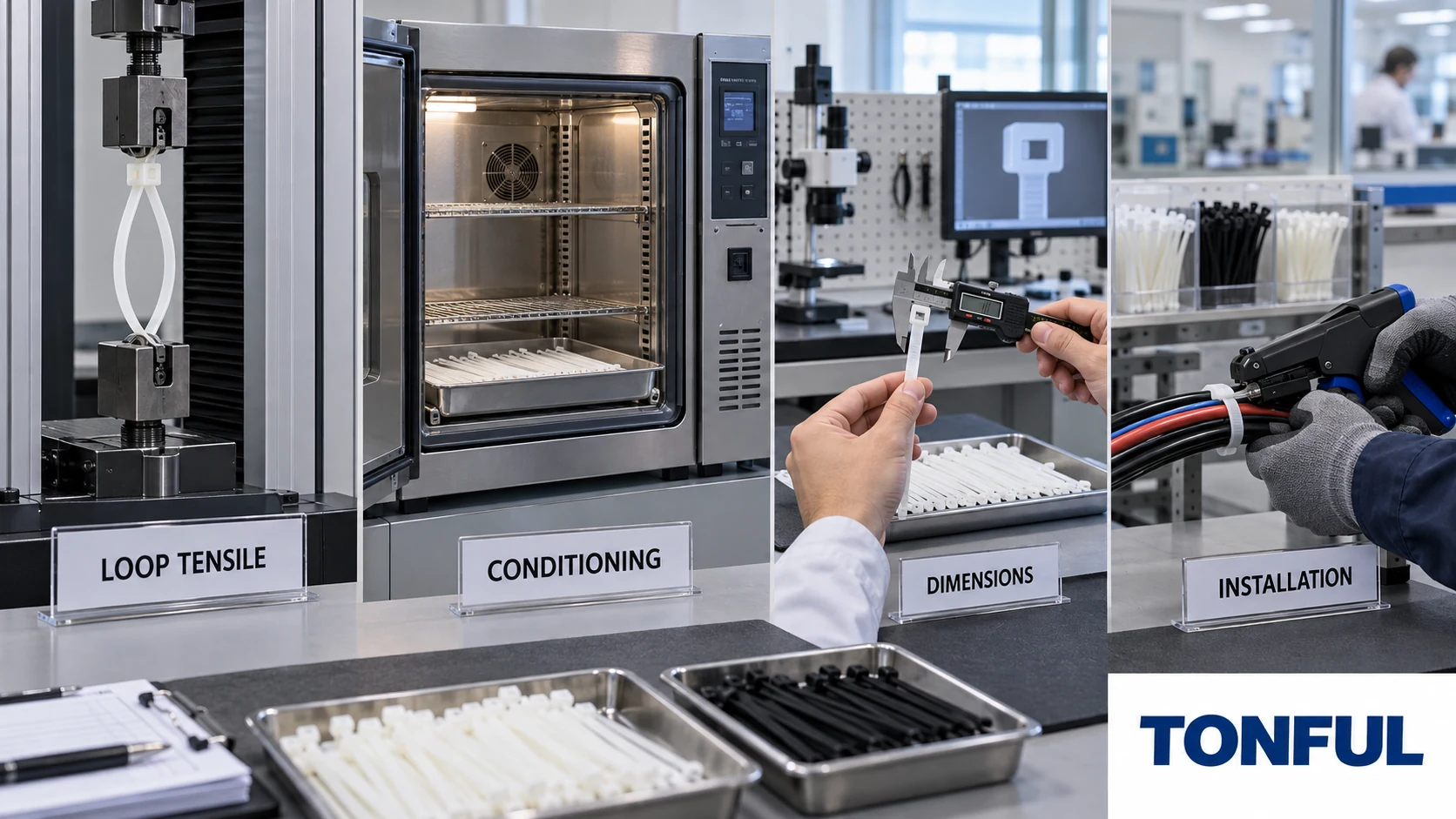
Cable tie testing should answer more than “How much force did it hold?” A useful plan connects specimen identity, conditioning, loop geometry, equipment, installation method, failure mode and acceptance source. Without those controls, a peak-force result cannot be compared reliably across lots, suppliers or materials.
This guide organizes loop tensile, locking, conditioning and installation verification for nylon and metal cable ties. It does not prescribe universal sample quantities, speeds or pass limits. Those values must come from the applicable standard, product drawing, customer specification or approved qualification plan.
Define the Test Purpose First
Qualification, supplier comparison, incoming inspection, process monitoring and failure investigation have different objectives. Qualification may include several environmental sequences and destructive analysis. Incoming inspection usually confirms identity and selected characteristics. Process monitoring tracks stability. A failure investigation preserves evidence and tests hypotheses rather than merely repeating the release test.
Write the decision before selecting equipment: what product and application will be approved, what evidence is mandatory and what result blocks release? Identify the cable tie family, material, size, revision, manufacturing site and lot. Include the intended bundle, tool and environment when the result is application dependent.
IEC 62275 covers metallic, non-metallic and composite cable ties and associated fixing devices for wiring systems. Use the applicable edition and purchased standard for exact classifications and methods; the public scope page does not supply a universal test recipe.
Build a Sample Allocation Plan
State sample quantity and the rationale approved by the responsible engineer or customer. Decide whether tests use independent groups or the same specimens in a sequence. Sequential exposure can represent service history, but it may hide which condition caused degradation. Independent groups isolate effects but require more samples.
Include an unaged reference group where comparison matters. Reserve samples for dimensional checks, loop testing, installation trials, environmental exposure and destructive examination. Identify every specimen before testing and preserve failed parts. Predetermine how replacement specimens are authorized.
An invalid test results from a documented setup or equipment problem, such as fixture slip outside the intended contact, not from an unfavorable valid failure. Record the reason, evidence and approver before retesting. Never discard a low result simply because another specimen passes.
| Sample group | Purpose | Required controls |
|---|---|---|
| Baseline | Initial dimensions, locking and mechanical reference | Lot, conditioning, measurement method |
| Conditioned | Moisture, temperature or other preconditioning | Chamber record, exposure, transfer time |
| Aged | UV, thermal, chemical, corrosion or vibration sequence | Method, duration, orientation and post-aging interval |
| Installation | Tool setting, cutoff and bundle interaction | Tool ID, operator, bundle and inspection |
| Retained | Comparison or dispute reference | Sealed identity, storage and custody |
Verify Identity and Dimensions
Before destructive testing, confirm label, part number, revision, lot, material designation, color or coating, manufacturing site and packaging condition. Measure overall and usable length, strap width and thickness, head envelope and relevant mounting features with equipment suited to the tolerance.
Inspect molded ties for incomplete fill, flash, tooth damage, pawl deformation, contamination, brittleness and color inconsistency. Inspect metal ties for burrs, sharp edges, lock deformation, coating gaps and mixed construction. Photograph a consistent view and identify the specimen in the image.
The cable tie moisture and storage guide is relevant when nylon conditioning can change behavior. The stainless steel cable tie guide explains why alloy, coating and lock identity must accompany metal-tie results.
Run the Loop Tensile Test
Control the Setup
Minimum loop tensile strength evaluates a closed tie and lock under a defined method. Record fixture or mandrel geometry, loop diameter, specimen orientation, pull direction, test speed, equipment model, load-cell range, resolution, accuracy and calibration status. The equipment range should provide meaningful resolution without risking overload.
Condition specimens as required and record ambient temperature and humidity during testing where applicable. Control the time between conditioning and test. Install the tie with the specified tool or method and setting. A hand-pulled loop may not represent production installation.
Do not convert MLTS into a safe working load or hanging capacity without an approved design method. The cable tie tensile strength guide explains this boundary, while the size-selection guide should be used to confirm bundle fit separately.
Record Failure Evidence
Record the complete force curve when useful, peak force and failure mode. Categories may include strap break, tooth shear, pawl release, head fracture, metal-lock slip, coating damage or fixture-related invalidity. Photograph the failed specimen and retain it with its ID.
A passing peak result can still reveal an undesirable mode or large variation. Review individual values, not only averages. Compare cavities, tools, lots and conditioning groups when traceability allows. Statistical treatment and capability decisions require a stable process and an approved sampling plan; a small qualification set does not establish production capability.
Check Measurement Suitability
Before relying on results, verify that the fixture does not cut, pinch or support the loop differently from the specified method. Run a documented setup check and confirm machine alignment. Review the relationship between equipment accuracy, resolution, repeatability and the acceptance limit; a display with many decimal places is not proof of adequate measurement capability.
When supplier and customer laboratories compare results, align specimen conditioning, installation tool, loop geometry, speed, preload, data-acquisition settings and failure definition before concluding that the product changed. If a measurement-system study, correlation exercise or uncertainty statement is required, define it in the qualification plan. Keep the reference specimens and raw force curves needed to investigate a laboratory-to-laboratory difference.

Conceptual test setup only—not an acceptance standard or traceable laboratory result.
Check Locking and Engagement
Locking inspection begins before maximum-force testing. Confirm correct tail insertion direction, tooth and pawl engagement, minimum approved loop, smooth tightening and resistance to unintended release. Releasable designs require a separate cycle and retained-function plan rather than the same assumptions as permanent ties.
For metal ball-lock or buckle designs, verify strap routing, lock seating, slip behavior and cutoff. If the design depends on a coating, inspect damage around the head and cut edge. For integral mounts, loop locking does not prove panel retention; test the fixing interface using the approved panel geometry and direction.
Measure reverse slip or displacement only when the method defines reference points, preload, rate and acceptance. Avoid subjective “feels tight” judgments. Record observable lock damage and whether the result occurred before, during or after environmental conditioning.
Control Conditioning and Environmental Exposure
Conditioning must identify temperature, humidity or immersion medium, duration, specimen state, packaging, orientation and transfer time. For nylon, distinguish material conditioning from environmental aging. A conditioned specimen is not automatically an aged specimen.
Environmental tests should reproduce project risks: UV, heat, cold, thermal cycling, chemicals, water, salt or vibration as applicable. Define actual fluids, concentrations, temperatures and exposure modes. For stainless products, corrosion depends on alloy, deposits, crevices and dissimilar metals; for polymers, formulation and stress state matter.
After exposure, allow only the recovery or stabilization defined by the method. Repeat dimensional, visual, locking and mechanical checks specified by the plan. Report both initial and aged results and the change where required. Do not use a generic aging condition to claim suitability for every outdoor, automotive, marine or chemical application.
The ETFE cable tie guide demonstrates why specialty-material claims still need finished-product testing. The cold-weather failure guide provides a failure-analysis context for low-temperature complaints.
Validate Installation Tools and Bundle Interaction
Test the complete installation process on production-intent minimum, nominal and maximum bundles. Record tool make, model, serial or asset ID, setting, verification status, blade condition, operator and work instruction. Confirm that tension and cutoff are repeatable.
Inspect insulation marks, cable deformation, hose restriction, sleeve damage, head orientation, tail projection and nearby interference. A tie can pass loop tensile testing and still damage a sensitive bundle. Data or communication cables, soft insulation and small conductors may require stricter deformation control than a rigid qualification mandrel reveals.
Tool settings are not automatically transferable between tie widths, materials or head designs. Challenge the lowest and highest approved settings when defining the process window. Include first-piece, tool-change, blade-change and restart verification where production risk justifies it.
Use a Complete Test Record
| Record field | Required entry |
|---|---|
| Test purpose | Qualification, incoming, monitoring or investigation |
| Sample identity | Part, revision, material, lot, cavity/site and sample ID |
| Allocation | Group, quantity, independent/sequential use and retained sample |
| Conditioning | Method, chamber, setpoints, actuals, duration and transfer time |
| Installation | Bundle/mandrel, tool ID, setting, operator and cutoff condition |
| Equipment | Machine, load cell, range, resolution, accuracy and calibration |
| Test setup | Fixture, loop geometry, direction and speed |
| Results | Raw values, peak, displacement if required and aged change |
| Failure evidence | Mode, photo ID, preserved sample and invalidity decision |
| Acceptance | Source document, limit, pass/fail, reviewer and date |
Keep raw machine output, photographs, chamber records and calibration references with the report. If data are corrected or excluded, preserve the original and document the reason, authority and revision. Trace the report to the released part and customer or project requirement.

A controlled test record connects each result to the specimen, setup, acceptance source and reviewer.
Interpret Results Without Overclaiming
A qualification pass applies only to the documented part, material, manufacturing process, site, conditioning, test sequence and application scope. It does not prove every size, color or related family. A supplier comparison is valid only when equivalent methods and conditions are used.
Investigate trends such as greater scatter, changing failure mode or tool sensitivity even when all samples exceed a limit. Define reaction rules for nonconforming results: lot containment, traceability review, equipment check, retest authorization, root-cause analysis and corrective-action verification.
Work With TONFUL
TONFUL’s cable tie range includes polymer, mounting and stainless designs. Send the controlled drawing, material, bundle, environment, test purpose, applicable method, acceptance source, sample quantity and reporting needs. TONFUL can review product options and sample evidence; final approval remains with the responsible project authority.