
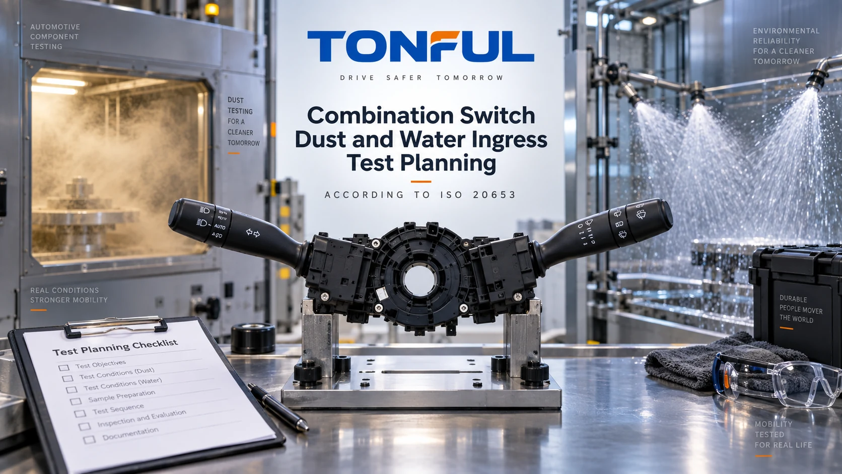
A dust-covered or water-sprayed combination switch is not automatically IP rated. An ingress claim depends on a defined enclosure, complete production configuration, specified IP code, controlled test method and post-test acceptance evidence. For a steering-column switch, the housing, stalk boots, shafts, connector interface, mating parts and installed orientation can all change the result.
ISO 20653 is useful because it provides road-vehicle IP-code definitions, requirements and confirmation tests. It does not assign one universal rating to every stalk switch, and it does not prove electrical endurance, chemical resistance or vehicle-level suitability. Buyers should start with the installation risk and customer requirement, then request evidence for the exact product.
On this page: Define the Claim | Plan Dust and Water Tests | Control Evidence | Release Checklist
Define the Claim
Understand What ISO 20653 Covers
ISO 20653:2023 applies to degrees of protection provided by enclosures of road-vehicle electrical equipment against foreign objects, access and water. The official ISO page confirms that the standard defines the codes, requirements and tests used to verify the relevant degree of protection. Its K designations address road-vehicle requirements beyond the base IEC IP framework.
The project must specify the exact code and standard edition. The first characteristic concerns foreign objects/access; the second concerns water. An X means that a characteristic is not specified in that designation, not that the product has passed every level. A higher-looking code should not be treated as a universal substitute because methods and exposure mechanisms differ.
Do not write “waterproof” when the available evidence supports only one controlled degree of protection. An IP result is not permission for immersion, pressure washing, steam, chemicals or repeated field exposure unless those conditions are actually within the approved requirement.
Fix the Enclosure Boundary
Define what was tested: left stalk, right stalk, complete combination-switch assembly, steering-column module or switch plus mating connector. Record housing revision, seals, boots, shafts, fasteners, vents, membranes, connector locks, cavity plugs and harness. A test on an empty housing does not release a populated electronic assembly.
Installation state matters. Some openings may be shielded by column trim; others may face upward, downward or toward a door opening. A connector may require a production mating half and seals to complete the enclosure. The combination switch pinout and connector guide helps control connector orientation and cavity identity, but the ingress plan must also define sealing components.
| Claim element | Required evidence | Unsafe shortcut |
|---|---|---|
| Exact IP code | Drawing/specification and applicable edition | “Automotive waterproof” |
| Enclosure identity | Part/revision and configuration photographs | Similar housing appearance |
| Mating condition | Connector, seals, plugs and harness | Unmated connector without rationale |
| Orientation | Vehicle mounting drawing and test fixture | Convenient chamber position |
| Operating state | Powered/unpowered and stalk actuation plan | Final visual check only |
| Acceptance | Controlled requirement and inspection method | “No obvious water outside” |
Plan Dust and Water Tests
Dust and Foreign-Object Protection
The plan should identify required degree, test dust, chamber condition, pressure condition where applicable, duration, sample orientation and whether the controls move during exposure. Use only parameters from the applicable ISO edition and customer specification; do not invent a universal dust mass or exposure time.
Before testing, photograph seams, boots, shaft entries and connector faces. Record operating force, detents, return, contact outputs or decoded states, insulation/leakage and communication as applicable. During or after exposure, check whether dust obstructs rotary rings, momentary return or self-cancel interfaces. Dust may be present without violating one requirement yet still impair function; acceptance must address both the IP criterion and product-specific performance.
If internal inspection is required, define opening method and contamination controls so teardown does not introduce particles. Record dust location, amount or coverage method, and proximity to contacts, resistors, PCB, optics or lubricant. One opened sample cannot be reused for another enclosure test unless the approved plan permits and restores it.
Water Protection
Water methods can represent dripping, spray, jets, high-pressure/high-temperature exposure or immersion depending on the specified code. They are not interchangeable. Define nozzle or apparatus, flow/pressure/temperature as applicable, distance, angles, duration, turntable or fixture motion, product orientation and operating state from the controlled method.
A steering-column switch may need multiple orientations or actuation while wet if the requirement calls for it. If actuation is included, define frequency and positions without creating an unrepresentative pumping mechanism. If the product is energized, monitor unintended turn-signal, headlamp, wiper or cruise requests as well as current and communication.
Post-test drainage and recovery can alter findings. Specify when external water is removed, when the enclosure is opened, and when electrical tests occur. Do not dry a sample until the required as-tested evidence is captured. Water discovered inside must be mapped to its entry path and affected parts; “still operates” may not satisfy the enclosure requirement.
Preconditioning and Sequence
Ingress performance can change after temperature cycling, vibration, mechanical endurance, connector mating or ageing. The approved plan should state whether ISO 20653 testing is on new samples or follows defined preconditioning. The environmental test plan for truck combination switches explains how to justify separate groups and accumulated-damage sequences.
Record every preconditioning exposure and intermediate inspection. A combined sequence can reveal seal wear but complicate attribution; independent groups isolate causes but may miss interaction. Sample allocation should be chosen before results are known.

Define every seal, opening, mating interface and vehicle orientation included in the claimed enclosure before testing.
Control Evidence
Use a Test Configuration Record
| Record field | Required entry |
|---|---|
| Sample identity | Part, revision, lot, sample ID and production-intent status |
| Claimed code | Exact IP designation, standard and edition |
| Enclosure boundary | Included housing, connector, seals, plugs and harness |
| Preconditioning | Mechanical, climatic, mating or endurance history |
| Mounting | Fixture drawing, orientation and exposed faces |
| Dust setup | Method, dust, chamber/pressure state, duration and actuation |
| Water setup | Apparatus, controlled parameters, angles, duration and actuation |
| Operating mode | Powered state, loads, communication and monitoring |
| Initial/final checks | Mechanics, function, electrical values and DTCs |
| Internal inspection | Opening time/method and ingress location evidence |
| Acceptance source | Drawing/specification/plan revision and criterion |
| Disposition | Pass, fail, conditional or invalid with justification |
Sample quantity must come from the customer requirement or approved qualification plan. Identify reference/control samples where needed. Test equipment and measurement devices need model, range, accuracy and calibration status. Photographs should have consistent orientation, scale and sample ID.
The mechanical endurance testing guide provides useful genealogy and failure-record principles. Ingress testing should not erase previous anomalies; preserve baseline and sequence history for each sample.
Separate Enclosure and Functional Decisions
Use two linked decisions. First, did the enclosure meet the specified ISO 20653 requirement? Second, did the product meet electrical, mechanical and diagnostic acceptance after exposure? A product can remain temporarily functional while unacceptable water is present, or show a functional problem without violating the particular ingress criterion. Both outcomes require investigation.
Post-test checks can include:
- housing, seal, boot, connector and marking condition;
- internal dust or water location and effect;
- stalk force, detents, return and rotary operation;
- each discrete, coded or networked function;
- contact voltage drop or resistance windows under controlled conditions;
- insulation/leakage where applicable;
- illumination, communication, current and DTC behavior;
- corrosion evidence after any required dwell or recovery.
The analog, resistive, LIN and CAN stalk guide helps choose architecture-specific electrical checks. Do not use a simple continuity test as complete evidence for an electronic module.
Investigate a Failure
Quarantine the sample and related build lot. Preserve external photographs before opening. Trace possible entry through parting lines, shafts, boots, fasteners, vents, connector interfaces or capillary paths. Compare dimensions, seal compression, material, assembly force and fixture condition with approved records.
Confirm whether the failure originated in design, component variation, molding, seal damage, assembly, test setup or preconditioning. Corrective action may require geometry, material, process, poka-yoke, inspection or test updates. Retesting a new sample without root-cause containment does not close the issue.

Inspect the identified sample before drying or teardown, then map any ingress to the exact enclosure path and affected function.
Release Checklist
- Target vehicle location and contamination risks are defined.
- Exact ISO 20653 code and edition come from a controlled requirement.
- The enclosure boundary includes all production mating and sealing parts.
- Test orientation represents installation and is documented by drawing/photo.
- Samples are production-intent, uniquely identified and properly allocated.
- Preconditioning and sequence are approved before testing.
- Dust and water apparatus parameters follow the controlled method.
- Powered state, actuation and monitoring are explicitly defined.
- Enclosure acceptance and functional acceptance are evaluated separately.
- Internal inspection preserves traceable ingress-location evidence.
- Failures follow containment, root-cause and corrective-action rules.
- Any IP statement is limited to the exact tested configuration and conditions.
Work With TONFUL
After exposure, retain photographs of seal position, leak path and affected circuit before disassembly. Sectioning can distinguish housing entry, connector-interface leakage and internal capillary travel; record the first observed ingress location instead of reporting only a final pass/fail result.
TONFUL’s automotive combination switch range provides current references for sourcing discussions. Share the vehicle installation, complete OE identity, enclosure drawing, connector/mating configuration, required ISO 20653 code, preconditioning sequence and acceptance criteria. TONFUL can review the candidate configuration and sample evidence against the project requirement; no IP rating should be assumed without a configuration-specific report.