
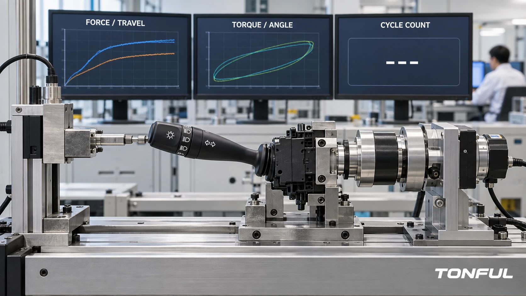
Combination switch mechanical endurance testing must reproduce the real hand motions, detents, momentary actions and return mechanisms defined for the project. A cycle count alone proves little if the state sequence, force or torque, travel, actuation point, speed, dwell, fixture alignment, sample quantity and failure criteria are missing. Electrical monitoring may be included, but this article focuses on mechanical life and degradation.
TONFUL supplies automotive combination switch references for multiple vehicle applications. Confirm the exact vehicle, complete OE reference, connector, pinout, function matrix, control architecture, approved sample and project-specific validation plan before ordering or testing.
Quick Evidence Matrix

Conceptual illustration only – not a vehicle procedure, laboratory result, universal limit, or acceptance standard.
| Work area | Required focus | Acceptance source |
|---|---|---|
| Define the Test Object and Architecture | Freeze part number, revision, lot, vehicle application, connector, function matrix and whether each channel is direct-load, relay-controlled, ground-side, resistance-coded or module interpreted. | Project specification, approved plan, or root-cause evidence |
| Define Actuation Loads and Travel | Document force/torque direction, application point, travel or angle, speed, dwell, return and measurement method for every control. | Product drawing, approved plan, or customer requirement |
| Define Mechanical Cycles and Actuation | State which turn-signal strokes, self-cancel actions, beam changes, wiper detents, washer pushes, cruise buttons and integrated functions form one sequence. | Project specification, approved plan, or root-cause evidence |
| Control Fixture Alignment | Record mounting, actuator geometry, side load, compliance, homing and challenge checks so the fixture does not create or hide failure. | Fixture drawing and validated procedure |
| Monitor Degradation During the Test | Define inspection intervals and continuously or periodically monitor function, contact path, voltage drop, resistance, output state, actuation, illumination, temperature and abnormal events as appropriate. | Project specification, approved plan, or root-cause evidence |
| Set Failure Criteria Before Testing | Acceptance criteria must come from the product specification, customer requirement, approved drawing or qualification plan. | Project specification, approved plan, or root-cause evidence |
The matrix defines evidence categories, not pass values. Unknown requirements must remain open until the document owner confirms them.
For every section below, identify the applicable component, circuit and sample, then retain objective evidence. Any numeric requirement must cite the product drawing, OEM or customer specification, qualification plan or approved test procedure. This rule is stated once here; the section-specific records below address different technical risks.
Define the Test Object and Architecture
Freeze part number, revision, lot, vehicle application, connector, function matrix and whether each channel is direct-load, relay-controlled, ground-side, resistance-coded or module interpreted. Include mating connectors, terminals and harness interfaces when the qualification plan treats them as part of the test system.
Architecture determines what endurance is actually exercising. A direct-load switch may interrupt lamp current at its contacts, while a relay-controlled switch may operate only the relay coil. A BCM input can be a discrete state, a resistance-coded value or a momentary request interpreted by software. Testing all three with the same load would create evidence for the wrong design. Build a channel map that identifies power, ground, outputs, encoded inputs, illumination and communication-related pins, then tie every monitored state to the controlled circuit document.
Define Actuation Loads, Travel and Return
Document the direction and point where force or torque is applied, the commanded travel or angle, actuation speed, dwell, release profile and rest time. A turn-signal stroke, beam pull, washer push, wiper-ring rotation and cruise button press are different mechanical actions and should not inherit one generic setting.
Measure initial force-travel or torque-angle profiles using identified equipment, range, resolution, accuracy and calibration status. Define peak force, detent force, holding force, return force, free play and hysteresis when required. Apply the load at the intended finger-contact zone unless the controlled method specifies another point; pushing near the stalk root creates a different bending moment from acting near the tip.
Electrical loading may still be required during cycling, but define it separately by channel. State whether each contact is unloaded, carries a relay request, switches a direct load or produces a coded/module input. Do not add a generic electrical load merely to make a mechanical test appear more severe.
Define Mechanical Cycles and Actuation
State which turn-signal strokes, self-cancel actions, beam changes, wiper detents, washer pushes, cruise buttons and integrated functions form one sequence. Define cycle count, rate, dwell, actuator force or travel, alignment, rest periods and whether electrical switching occurs during movement. Avoid a fixture that side-loads the shaft or masks weak detents.
Describe one cycle as an explicit state sequence. A turn-signal example might be neutral to left latch, controlled self-cancel, neutral, right latch, controlled self-cancel and neutral. A wiper-ring sequence can progress through every specified detent and return in the approved order. A momentary washer or flash action needs a defined travel, dwell and release. State which contacts are energized at each transition. A cycle counter should advance only after the sequence is complete; retries, fixture stops and partial movements need separate event codes. Use position sensing when an actuator command alone cannot prove that the stalk reached the required detent.
Control Fixture Alignment and Test Validity
Record the production mounting interface, fasteners, support, switch orientation, actuator-tool revision, home position and alignment datums. Verify that the tool follows the intended motion without twisting the housing, rubbing adjacent controls or adding side load. Challenge the fixture before the test by confirming positions, forces and sensor responses with a reference or approved setup.
Separate product failure from fixture failure. A loose clamp, worn actuator tip, encoder drift, broken external harness or missed home command can invalidate data without proving that the switch failed. Define pre-run checks, periodic challenge checks, interruption rules, cycle-credit decisions and authorization for repair or retest. If temperature or another environment is part of the approved endurance plan, record the actual condition and recovery state, but do not import a generic environment into every mechanical test.
Monitor Degradation During the Test
Define inspection intervals and continuously or periodically monitor function, contact path, voltage drop, resistance, output state, actuation, illumination, temperature and abnormal events as appropriate. Preserve the first cycle and condition at which chatter, missed state, intermittent open, heat or mechanical damage appears.
Select monitoring by architecture. A direct-load path may need current, loaded voltage drop and temperature trending; a relay request may need coil-current or output-state confirmation; a resistance-coded input may need measured value and decoded state. Correlate electrical data with commanded position and cycle number. Sampling too slowly can miss contact bounce or intermittent opens, so the acquisition method and event threshold must be justified against the failure being sought.
Set Failure Criteria Before Testing
Acceptance criteria must come from the product specification, customer requirement, approved drawing or qualification plan. Address functional errors, electrical limits, unstable states, temperature evidence, mechanical damage, symbol or illumination failure, connector damage and post-test performance. Never create limits after seeing results.
Separate a test interruption from a product failure. Loss of chamber control, fixture misalignment, broken external wiring or acquisition failure may invalidate an interval without proving the switch failed. The approved procedure should define who can declare a test invalid, what evidence must be retained, whether completed cycles remain creditable and when replacement samples or retesting are allowed. A failed sample should not be repeatedly operated until its first-failure condition is lost.
Failure Evidence Matrix
Use the matrix below to connect an observed condition with evidence and containment. It is a diagnostic framework, not a list of universal rejection thresholds.
| Observed condition | Evidence to capture | Immediate action | Possible investigation path |
|---|---|---|---|
| Missed or incorrect switch state | Commanded position, decoded state, contact channel, cycle and timestamp | Pause according to the approved plan and preserve the state | Verify fixture travel, pin mapping, contact continuity, resistance-coded value and module interpretation |
| Intermittent open or contact chatter | High-speed voltage/current trace, actuator position and event duration | Protect the load and mark the first event | Repeat only as authorized; examine contact wear, spring force, contamination and terminal stability |
| Rising contact resistance or voltage drop | Initial, interim and final readings; test current; probe points; temperature | Review trend and affected channels | Confirm measurement system, isolate switch from connector losses and inspect contact surfaces |
| Abnormal temperature rise | Sensor location, ambient, load, current, voltage drop, thermal image and cycle | Stop at the safety threshold defined by the plan | Check contact resistance, terminal grip, connector fit, wiring impedance and excess load |
| Detent, return or actuator degradation | Force/travel trace, position repeatability, video and physical inspection | Prevent further cycling from erasing the condition | Inspect springs, cams, lubrication, shaft alignment, housing and fixture side load |
| Illumination or symbol failure | Supply condition, brightness/function result, visual record and cycle | Identify whether the fault affects safety or test continuation | Separate LED/lamp, resistor, solder, terminal and optical-component causes |
| housing, stalk or mounting damage | Setup photographs, crack or wear location, fixture loads and environment | Preserve parts without disassembly until review | Compare mounting geometry, actuator alignment, material condition and environmental sequence |
| Connector or terminal damage | Mating-cycle history, terminal position, retention evidence, heat marks and harness support | Quarantine the sample and mating interface | Inspect terminal engagement, retention, plating, strain, contamination and connector compatibility |
Test or Investigation Record

This conceptual record layout supports traceability; it does not replace the controlled test or investigation form.
Use a vertical record that remains readable on mobile screens and can be transferred into a laboratory form:
| Record field | Required entry |
|---|---|
| Sample identity | Part number, revision, manufacturing lot, sample ID, build status and approved deviation |
| Application and channel | Vehicle or project, connector, pin, function and control architecture |
| Electrical load | Voltage, current or signal, load type, inrush or release condition, protection and wiring impedance |
| Cycle sequence | Switch actions, energized state, rate, dwell, planned cycles and completed count |
| Fixture and environment | Actuator-tool revision, orientation, conditioning, exposure sequence and actual chamber profile |
| Monitoring | Equipment ID, range, accuracy, calibration status, and probe or sensor locations |
| Results | Initial, interim and final measured values with raw-data reference |
| Failure | First failure cycle, test condition, symptom, immediate containment and preserved evidence |
| Validity and retest | Interruption or invalid-test reason, disposition, approving authority and retest scope |
| Approval | Acceptance-source document and clause, pass/fail, reviewer and date |
For example, an electrical-load entry should identify the approved load profile rather than say only “lamp,” and a failure entry should record the first affected cycle and evidence file rather than only “failed.” Define sample quantity, equipment suitability, invalid-test rules, retest authority and data retention before execution. A summary pass/fail field cannot replace raw readings and photographs.
The official ISO pages describe distinct environmental-load categories for road-vehicle electrical and electronic equipment: ISO 16750-2:2023 covers electrical loads, ISO 16750-3:2023 covers mechanical loads, and ISO 16750-4:2023 covers climatic loads. Apply a part only when the project or customer specification selects it, then confirm the applicable edition, mounting location, method, severity, sequence and acceptance source. These standards do not by themselves establish a universal combination-switch cycle count, contact-resistance limit, vibration severity, temperature limit or release criterion.
Internal Links and Decision Path
Continue with TONFUL’s product range, contact test, failure guide, OE guide and truck selection checklist.
Supplier, Release, and Change Control
For an RFQ or validation request, provide the vehicle, OE chain, connector, function matrix, architecture, load definition, environment, sample quantity, test plan and acceptance sources. Request controlled drawings, raw-data references, nonconformance handling and change notification.
Receiving inspection should compare lot identity, housing, connector, terminals and functions with the approved sample. Define reaction plans for discrepancies and changes that may require notice or reapproval.
Final Release Checklist
- Scope, application, part revision, sample quantity and lot are identified.
- Electrical architecture, functions, loads, environment and conditions are documented.
- Equipment, fixtures, probes, ranges, accuracy and calibration status are recorded.
- Actual results, failure modes, photographs and raw-data references are retained.
- Every limit points to an approved source; no universal value is invented.
- Invalid tests, retests, deviations and unresolved items have documented disposition.
- Approved sample, receiving controls, traceability and change notification are defined.
- Release identifies reviewer, date, approved scope and closure evidence.
Planning, Evidence Review, and Test Purpose
Before Execution
Before testing, confirm channel coverage, fixture validity, safety, data versions and acceptance sources.
After Testing
Retain sample identity, setup, calibration, readings, event logs and source clauses. Assign open items an owner and closure evidence.
Qualification vs Audit vs Production Monitoring
Distinguish qualification, audit and production monitoring; record each activity’s purpose, sample source and authority.
Preserve failures, identify design/process/test causes and review changes for regression testing or reapproval.
Work With TONFUL
Send TONFUL the complete application and evidence package rather than only a switch photograph or symptom. TONFUL can compare the request with current combination-switch applications and OE references, then align sample review and project-specific validation requirements. Final approval remains tied to controlled documentation, agreed tests and the approved sample.