
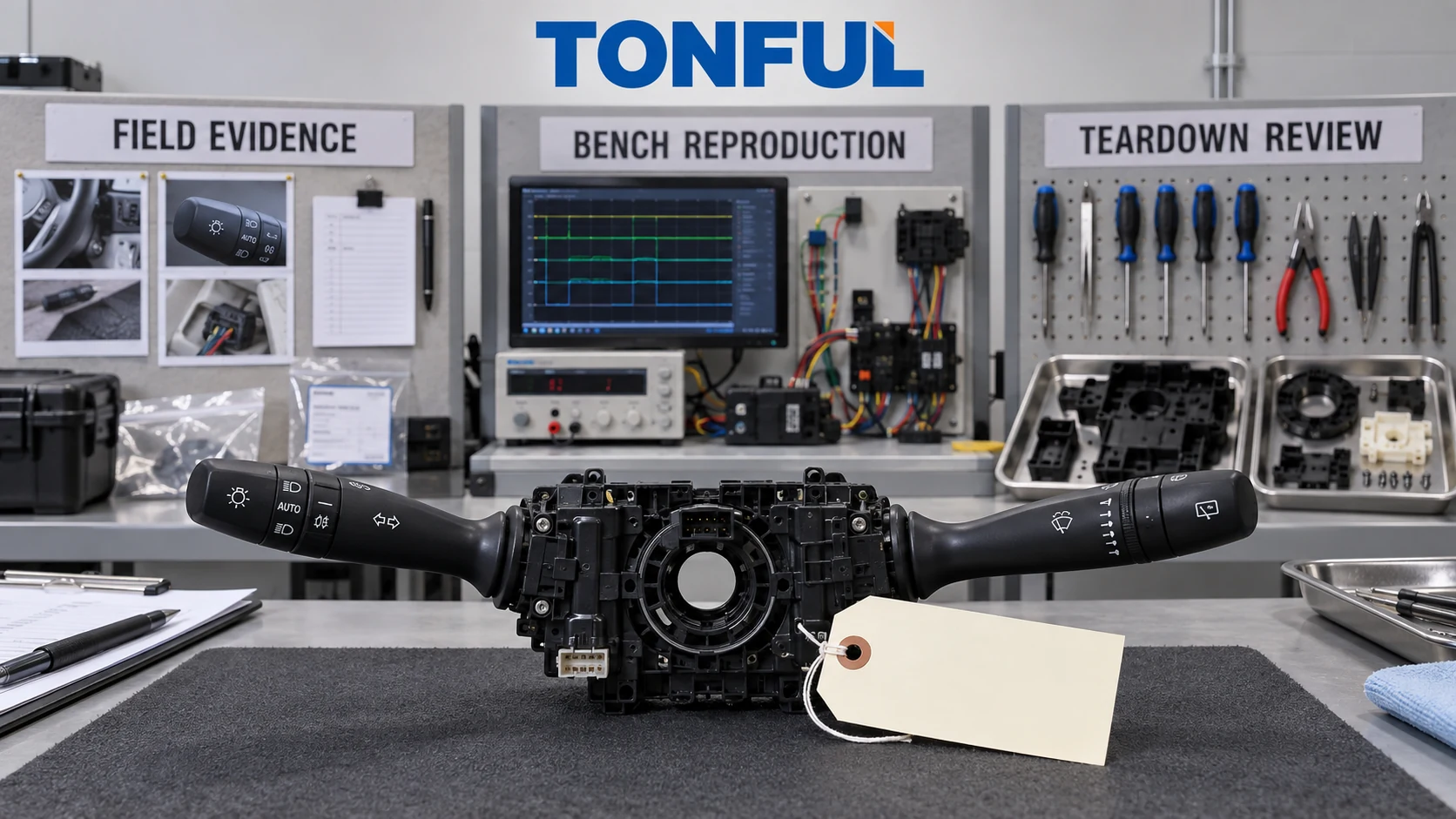
A returned combination switch that passes one room-temperature continuity check is not automatically “good.” The reported fault may depend on load, temperature, vibration, steering position, software state, connector movement or a specific sequence. Equally, replacing a stalk does not prove the removed part caused the complaint; the real fault may be in power, ground, terminals, relays, modules, motors, lamps or vehicle configuration.
An effective warranty process preserves the customer’s symptom, reproduces the system conditions, isolates the switch from surrounding circuits and closes the root cause. “No trouble found” (NTF) should be a controlled outcome with documented test coverage and remaining hypotheses, not a default label for a unit that passed an incomplete bench test.
On this page: Classify Returns | Follow the Diagnostic Flow | Control NTF Decisions | Close Corrective Action
Classify Returns
Separate Complaint, Failure and Cause
The complaint is what the driver or technician observed: intermittent indicators, no high beam, wipers that will not park, cruise buttons that do not respond, hot connector odor or a loose stalk. The failure mode is the measurable loss, such as an open contact, excessive loaded drop, wrong coded output, missed network message or broken return mechanism. The cause is the physical or process reason.
Do not convert “wipers failed” directly into “bad combination switch.” The wiper-switch failure guide shows how motor, park circuit, relay, BCM, wiring and washer conditions can produce similar symptoms.
| Return category | Example evidence | Disposition direction |
|---|---|---|
| Confirmed product failure | Repeatable wrong output, broken mechanism or internal damage | Root cause and corrective action |
| Vehicle/interface failure | Backed-out terminal, weak ground, relay/module/motor fault | Route to responsible system |
| Application mismatch | Wrong OE variant, pinout, voltage or feature matrix | Catalog/release correction |
| Handling/installation damage | Forced key, bent terminal, impact or contamination | Process/service investigation |
| NTF after complete coverage | Complaint not reproduced and all planned evidence passes | Preserve data and monitor trend |
| Insufficient evidence | Missing part, vehicle data or test conditions | Open/inconclusive, not NTF |
Recognize Common Product Failure Modes
Mechanical complaints include broken or weak return, poor detent, excessive play, self-cancel damage, stuck rotary rings and worn legends. Electrical complaints include intermittent contacts, high resistance, arcing, resistor drift, illumination failure and short/open circuits. Electronic versions add resets, sleep-current problems, software/configuration mismatch and LIN/CAN communication faults.
Heat damage requires special handling. Photograph the connector before separation and identify whether discoloration begins at the switch contact, header-terminal interface, crimp or harness. A melted housing can be secondary evidence; teardown should distinguish local resistance from excess current or downstream fault.
Follow the Diagnostic Flow
Preserve Field Evidence
Collect claim number, vehicle/VIN context, market, mileage/hours, production date, switch OE/suffix, replacement history, DTCs, freeze-frame/network data, environment and driver wording. Ask whether the symptom was hot/cold, after rain, during steering adjustment, with trailer/body equipment, or after repair.
Request connector photographs before disturbance, video where useful, wiring modifications and technician measurements. Record whether the replacement changed the symptom and whether the removed part was tested in the original vehicle. Package the returned part to protect connector, stalks and evidence.
The OE number cross-reference guide helps classify application mismatch and supersession evidence. An incorrect variant can function partially and still create a warranty return.
Run a Layered Investigation
- Quarantine and identify the part, lot and claim.
- Review complaint, vehicle scope, OE chain and previous repairs.
- Inspect housing, stalks, connector, terminals, contamination and heat.
- Reproduce the complaint at vehicle/system level when safe and possible.
- Verify power, ground, protection, harness, modules and downstream loads.
- Test every stalk state using the correct architecture and conditions.
- Add temperature, vibration, load or sequence only from the approved plan.
- Teardown after non-destructive evidence is preserved.
- Confirm root cause and affected population.
- Implement and verify corrective action.
For contact paths, compare continuity with loaded voltage drop because an oxidized interface may pass a low-current meter check. For resistor-coded inputs, retain raw resistance/voltage and decoded module state. For network switches, monitor power, wake, communication, software, DTCs and actual command messages. The analog, resistive, LIN and CAN stalk guide provides architecture boundaries.
Use a Symptom-to-Evidence Matrix
| Symptom | Possible switch direction | Non-switch alternatives | Next evidence |
|---|---|---|---|
| Intermittent turn signal | Contact, connector or coded input | Lamp/load, ground, BCM, harness | Input and output during wiggle/vibration |
| High beam or flash fails | Separate contact/state | Relay, lamp driver, coding | State matrix and downstream command |
| Wipers do not park | OFF/park request | Motor park contact, relay, module | Input, output and motor park trace |
| Washer works, wipe does not | Wipe-after-wash input/logic | Relay, motor or controller | Request and downstream output |
| Stalk will not cancel | Cancel interface damage | Steering geometry/install position | Mechanical inspection in fixture |
| Connector overheats | Contact/header resistance | Terminal, crimp, overload/short | Loaded drop, current and heat origin |
| Cruise buttons ignored | Coded/network state | Vehicle authorization, DTC/configuration | Raw state and module data |
| Fault after replacement | Wrong variant/software | Installation or vehicle fault | OE/pinout/architecture comparison |

Preserve field evidence and isolate the complete vehicle path before opening the returned switch.
Control NTF Decisions
Define NTF Correctly
AIAG’s CQI-14 Automotive Warranty Management describes a warranty-management framework and includes NTF case-study/decision-tree resources. It does not provide a combination-switch pinout or replace customer-specific warranty requirements.
An NTF decision should mean the complaint was not reproduced after the approved test coverage was completed on an identified part. It should not mean “continuity passed,” “no visible damage” or “vehicle unavailable.” Missing evidence is inconclusive.
Use a Reproduction Record
| Record field | Required entry |
|---|---|
| Claim/part identity | Claim, sample, part/revision, lot and vehicle |
| Customer wording | Verbatim symptom and frequency |
| Trigger conditions | Temperature, load, steering, vibration, moisture, sequence |
| Vehicle evidence | DTCs, wiring, module data, connector and repair history |
| Bench setup | Supply, loads, support modules, harness and software |
| Test coverage | Functions, cycles, temperatures and monitoring |
| Observed result | Reproduced/not reproduced with raw evidence |
| Teardown | Authorization, findings and photo/file IDs |
| Remaining hypotheses | Untested or vehicle-dependent conditions |
| Disposition | Confirmed, system-related, application, NTF or inconclusive |
| Review | Engineering/quality approval and date |
Use known-good comparisons carefully. The reference must have the same hardware, software, OE variant and setup. Swapping parts between vehicles can be useful, but record which symptom follows the part and control coding or initialization.
NTF units should remain available for trend analysis when policy permits. Cluster claims by symptom, vehicle, part revision, lot, environment, mileage and repair. A pattern may reveal a narrow condition that single-unit bench testing missed.
Prevent False NTF
Do not clear DTCs before capture. Do not clean contacts, cycle the stalk repeatedly or remate the connector before documenting initial state. Avoid tests that mechanically “heal” fretting or redistribute contamination. If shipping damage is possible, document packaging.
Intermittent monitoring needs adequate acquisition speed and threshold. A final pass cannot reveal a brief open circuit. Temperature and vibration tests should follow an approved diagnostic plan, not arbitrary stress intended to force failure.

Link the returned part, vehicle record, test setup and raw result so an NTF decision remains auditable.
Close Corrective Action
Convert Root Cause into Prevention
A confirmed design cause may update contact geometry, materials, lubrication, sealing, mechanism or electronics. A manufacturing cause may update tooling, crimping, assembly, poka-yoke, test coverage or maintenance. An application cause may require catalog, OE cross-reference, packaging and distributor controls. A vehicle-interface cause should be routed with evidence rather than charged to the switch.
Connect the action to Process Flow, PFMEA, Control Plan, Work Instruction and Inspection Record. Define containment population, owner, due date and verification. Confirm effectiveness with production-intent samples and field/warranty monitoring; closing an 8D at implementation is not evidence of recurrence prevention.
The combination switch manufacturer audit checklist provides evidence fields for traceability, change control and corrective-action closure.
Warranty Release Checklist
- Customer wording and trigger conditions are preserved.
- Vehicle, OE, switch and lot identity are complete.
- Connector/DTC evidence was captured before disturbance.
- Application mismatch and installation damage were evaluated.
- Switch input is separated from module, relay and downstream load.
- Testing matches contact, coded or network architecture.
- Intermittent conditions are monitored, not inferred from final checks.
- Teardown follows non-destructive evidence capture.
- NTF is used only after approved coverage; missing data is inconclusive.
- Root cause links to containment, permanent action and effectiveness.
Work With TONFUL
An NTF result should trigger a coverage review, not automatic return to saleable stock. Compare the field complaint with the laboratory sequence: temperature, vibration, supply state, module configuration, harness movement and actuation rate may be absent from a short room-temperature bench test. If the original condition cannot be reproduced, document which conditions were attempted and which remain unknown.
Preserve software, fixture and test-program revisions with the result. Otherwise, a later method change can make apparent trends incomparable and hide whether improved reproduction came from the product, the vehicle data or the laboratory process.
TONFUL’s automotive combination switch range supports application and sample discussions. For a warranty investigation, provide the exact OE reference, vehicle scope, claim wording, photographs, connector evidence, DTCs, circuit architecture and returned-part identity. TONFUL can compare controlled samples and product evidence; a replacement outcome alone is not treated as proof of switch root cause.