
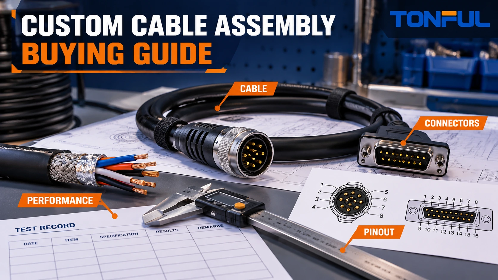
A custom cable assembly is not defined by two connectors joined by a length of cable. Its performance depends on the cable construction, conductor or pair assignment, shield and grounding strategy, connector interfaces, termination geometry, strain relief, routing and verification method. A sample can pass a basic continuity check while failing the intended data rate, current path, flex life, sealing or electromagnetic environment.
Buyers should specify the assembly as one controlled system. This guide organizes the RFQ and approval process around five decisions: choose the cable construction, define both connector ends, control the pinout and shield, engineer the mechanical interface, and verify the performance that matters in the final equipment.
On this page: Cable construction | Connectors | Pinout | Mechanical design | Testing | RFQ
Select the Cable Construction From the Signal and Environment
Start with the electrical function. Power conductors, low-level analog signals, discrete control, USB, industrial Ethernet, coaxial RF and machine-vision links impose different construction requirements. Record voltage and current where applicable, signal type, data rate or frequency range, allowable loss or drop, grounding concept and any required separation between circuits.
Then define the physical cable:
| Cable field | Required buyer definition | Risk when omitted |
|---|---|---|
| Conductors | Count, gauge/cross-section, stranding and material | Current, flexibility or termination mismatch |
| Insulation | Material and project-required electrical/temperature evidence | Incompatibility with voltage, heat or processing |
| Pairing | Pair IDs, twist requirements and untwist limit | Crosstalk or signal-integrity variation |
| Shield | Foil, braid, combination, coverage evidence and drain wire | Inconsistent EMC or termination behavior |
| Fillers/binders | Required geometry and flexibility | Cable deformation or unstable pair position |
| Jacket | Material, diameter, color/marking and environmental evidence | Fit, abrasion, chemical or flex failure |
| Approved source | Manufacturer part or controlled custom construction | Uncontrolled substitution between lots |
Do not select jacket material from a generic “PVC versus TPE” label. The exact formulation, wall, cable geometry and qualification conditions determine behavior. Likewise, a braid percentage or impedance value is meaningful only with a defined test method, frequency and construction.
UL Solutions’ official wire and cable overview describes testing and certification across wire and cable categories. A UL mark or style applies only within its documented scope; it does not automatically certify a finished cable assembly, connector termination or end equipment. Request the exact file, style or report only when the project requires it.

Conceptual illustration only—not an acceptance standard or certified cable cross-section. Use the controlled cable specification and supplier evidence.
Define Connectors and Termination Details
Specify each end independently. “M12 to RJ45,” “USB cable” or “circular connector cable” does not define keying, gender, pin count, coding, shell, contact plating, locking, orientation or panel interface. Record the connector manufacturer and full part number where mandated, mating reference, backshell, boot, contacts, seals and accessories.
For crimp contacts, match conductor and insulation to the contact’s approved range and application tooling. For solder cups, define wire preparation, soldering requirement and inspection criteria. For insulation-displacement, piercing or mass-termination interfaces, specify cable geometry and equipment. A housing can mate correctly while the selected contact, plating or termination process remains wrong.
Alternative connectors require a controlled qualification. Compare mechanical envelope, keying, contact system, material, plating, electrical rating, environmental evidence, mating cycles, sealing and applicable documentation. A supplier’s “compatible” statement should not replace mating samples and project validation.
Where overmolding is used, define material, color, shape, datum dimensions, cable exit direction, permitted flash, adhesion/retention method and marking. Overmold design must accommodate the connector and cable without damaging seals, disturbing shields or creating an abrupt flex hinge. TONFUL’s overmolded cable assembly and strain-relief guide provides a deeper DFM framework.
Control the Pinout, Pairs, Shields and Grounding
A pinout should identify both connector end views in a declared orientation. Use connector IDs, cavity numbers, circuit names, conductor colors or IDs and cable element references. Do not rely on a perspective product photo or assume that two connectors use the same numbering direction.
| End A | Cable element | End B | Function | Special control |
|---|---|---|---|---|
| A1 | Conductor/pair ID | B project cavity | Project-defined | Gauge, color or polarity |
| A2/A3 | Pair ID | B project cavities | Differential pair | Pair polarity and untwist control |
| Shell/drain | Shield/drain | Shell or project ground | Shield path | 360-degree, pigtail, one-end or both-end termination |
| Unused | No connection or reserved | As defined | Project-defined | Isolation and test-matrix treatment |
Preserve pair identity through preparation and termination. Excessive untwist or asymmetrical routing can alter balance and crosstalk. For coaxial assemblies, control center conductor, dielectric, shield preparation and connector launch geometry. For shielded multi-core cables, define whether foil, braid and drain terminate together and how the shield bonds to the connector shell or equipment ground.
The TONFUL foil-versus-braided shielding guide explains construction tradeoffs, but the product design must specify the grounding and termination strategy. “Shield connected” is incomplete when the termination style and reference plane affect performance.
Pinout revisions should be machine-readable for test programming and human-readable for assembly and inspection. If the drawing, cable schedule, connector datasheet and test program disagree, quarantine the release until the design authority resolves the conflict.

Conceptual illustration only—not a universal connector pinout. The approved drawing controls cavity numbering, pair assignment and shield termination.
Engineer Length, Flex and Strain Relief
Define finished length using stated datums: connector mating faces, backshell shoulders, cable exits or another controlled point. Include tolerance and measurement condition. Coiled, curved or highly flexible cables may require conditioning before measurement. If branches or breakouts exist, dimension each from a common datum and define orientation.
Minimum bend radius is not one universal multiple for every cable. Use cable and connector evidence for static installation, repeated flex, torsion or cable-carrier motion. A cable can be electrically suitable but too stiff for the equipment. Record moving length, bend direction, speed, acceleration, cycle target, torsion and temperature when dynamic service is required.
Strain relief should transfer load without concentrating stress at the conductor termination. Verify cable retention, bend transition, boot/overmold geometry and connector hardware. Avoid clamps that crush the cable or change controlled geometry. For panel-mounted connectors, confirm panel thickness, cutout, torque source and service access.
Routing requirements should include clearance from sharp edges, heat, moving parts and electromagnetic noise sources. A jacket does not remove the need for clips, glands or protective conduit. The final equipment remains responsible for supporting the cable and preserving bend and environmental limits.
Match Tests to the Required Performance
Continuity and miswire tests are fundamental production controls. The test matrix should include every intended path, prohibited short and shield connection. Record assembly ID, drawing and test-program revisions, fixture ID, equipment/calibration status and result. Continuity alone does not prove the following performance:
- Contact or path resistance under a defined setup.
- Insulation resistance or dielectric withstand.
- Voltage drop and temperature rise under load.
- Impedance, insertion loss, return loss, crosstalk or pair balance.
- Shield effectiveness or transfer impedance.
- Connector retention, cable pull, flex or torsion endurance.
- Ingress, chemical, temperature, vibration or functional performance.
For high-speed assemblies, define frequency range, cable length, fixtures, reference planes, de-embedding and acceptance source. TONFUL’s impedance-matching guide for high-speed cable assemblies explains why a nominal cable impedance does not prove the completed connectorized channel.
For USB or HDMI projects, identify the exact protocol generation, power function, connector variant and compliance scope. The TONFUL custom versus off-the-shelf USB and HDMI guide outlines when a controlled custom build is justified. Do not advertise logo-program compliance or data performance without the required authorization and evidence.
Testing records should state sample quantity, sample allocation, conditioning, equipment range/accuracy, fixture, test parameters, initial and aged results, invalid-test rules, acceptance-source document and reviewer. Qualification evidence does not automatically define 100% production tests; the control plan must identify coverage and reaction rules.

Conceptual validation matrix. Tests and acceptance values must come from the approved product specification and qualification plan.
Control Materials, Revisions and Production Lots
The BOM should identify the cable, connectors, contacts, backshells, hardware, labels, boots and overmold materials. Mark manufacturer-controlled parts separately from supplier-selected consumables. Require approval before changing cable source, conductor/insulation construction, shield, contact plating, connector resin, termination tooling, molding compound, test fixture or production site where these can affect form, fit or performance.
First-article inspection should confirm part identity, dimensions, orientation, pinout, termination workmanship, labels and test results. Production traceability should connect the finished assembly to its revision, cable and connector lots, process/test records and shipment at the level required by the project.
For data and imaging systems, functional tests can depend on host, software, power and equipment configuration. The TONFUL machine-vision cable guide demonstrates why the complete application boundary should be recorded rather than assigning every failure to the cable.
Custom Cable Assembly RFQ and Release Checklist
| RFQ category | Information to provide |
|---|---|
| Application | Equipment, installation location and service conditions |
| Electrical/signal | Power, signal type, protocol, data rate/frequency and grounding |
| Cable | Controlled part/construction, length, tolerance, jacket, shield and flexibility |
| End A/End B | Connector, contacts, keying, orientation, accessories and mating references |
| Pinout | End-view orientation, cavity map, pair/polarity and shield/drain treatment |
| Mechanical | Exit direction, overmold/boot, bend, retention, panel and routing constraints |
| Environment | Temperature, fluids, ingress, UV, vibration, flex and cleaning exposure |
| Verification | Qualification, first-article and production-test methods and acceptance sources |
| Quality/supply | Traceability, labeling, packaging, change control and deviation response |
| Commercial | Samples, forecast, order quantity, tooling/NRE and delivery requirements |
Release the exact product revision and scope. Sample approval does not automatically approve mass production, every cable length, every connector option or every host system. Conditional approval should identify the deviation, quantity, owner, closure evidence and expiration.
Discuss a Custom Cable Assembly With TONFUL
Send TONFUL the cable specification, connector references, pinout, length and tolerances, shield/grounding plan, routing and environment, applicable test plan, sample quantity and forecast. TONFUL can review termination, overmold, sourcing and verification requirements against the defined project. Final performance, compliance and production claims should remain tied to approved evidence for the exact assembly.