
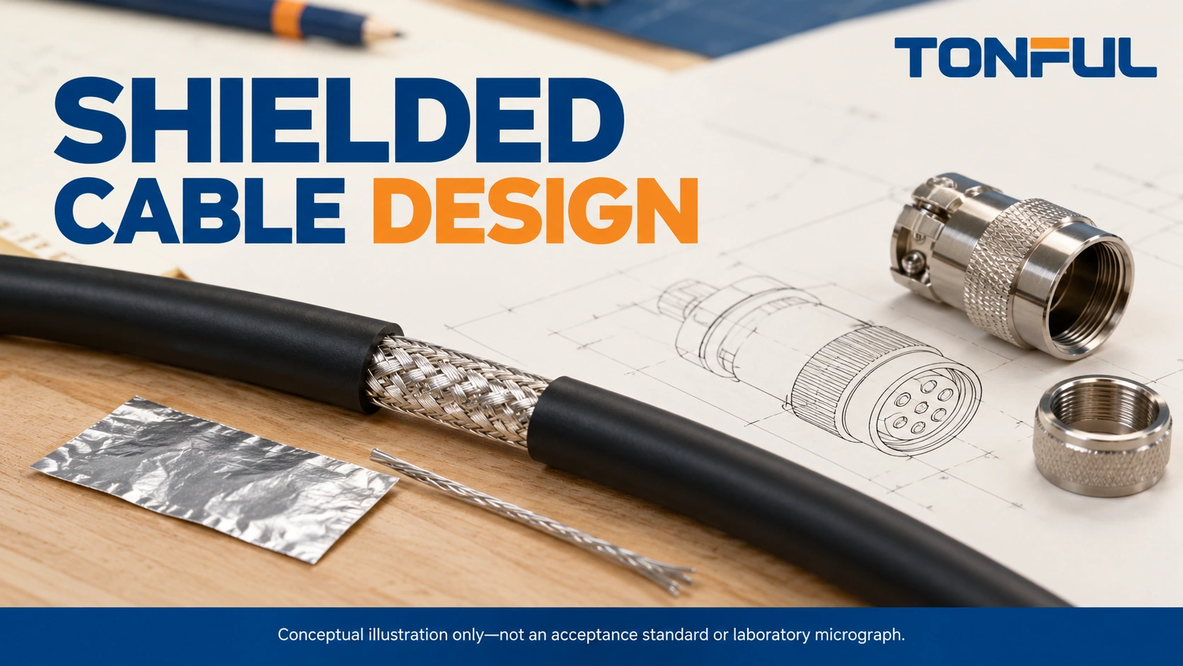
Shielded cable assembly design is a system decision. A cable can contain a substantial metallic screen yet perform poorly when its termination, connector shell or equipment bond leaves the intended noise-current path uncontrolled. Choosing foil or braid is therefore only one part of specifying the finished assembly.
Begin with the signal interface, interference environment, movement and equipment grounding architecture. Then define the cable construction, each termination and the evidence required for release. This guide compares practical options and provides a reusable shielding record without assigning universal frequency limits, attenuation figures or grounding rules to every application.
On this page: Design inputs, Construction comparison, Termination and grounding, Validation, TONFUL enquiry.
Define the Interface and the Interference Problem
Identify the intended signal and unwanted coupling
Record the actual interface: low-level analog, digital control, industrial network, RF coaxial link or another defined circuit. Signal bandwidth, switching edge behavior, impedance, receiver sensitivity and cable length influence the engineering review. A low data rate alone does not prove that only low-frequency interference matters.
Describe the noise sources and likely coupling paths. Nearby motor drives, switching supplies and parallel power cables can create different problems from an internal channel-to-channel interaction. Separate emissions from susceptibility: preventing a cable from radiating and protecting its signals from an external disturbance are related but not identical validation objectives.
Before adding a shield, review pair balance, twisting, routing, separation and circuit return paths. A shield is not a substitute for an incorrectly assigned return conductor or unsuitable interface. Keep any high-speed impedance requirement in the cable specification; changing shield layers or dielectric construction can alter electrical characteristics beyond simple continuity.
Define the installation and responsibility boundaries
Identify both equipment ends, intermediate connectors, branch points and moving sections. Record what the assembly supplier controls and what the installer or equipment manufacturer provides. A cable vendor cannot establish the quality of a painted enclosure bond or an undocumented connector adapter outside its supplied scope.
Distinguish signal reference, chassis bond and protective earth. They may connect at designated points, but they are not interchangeable labels. Do not use a drain wire as an assumed protective conductor or remove a required safety earth to reduce noise. Qualified personnel must follow the equipment’s safety and grounding documentation.
The wire gauge selection guide supports the separate review of conductor load and voltage drop. A cable’s shielding specification does not establish the current capability of its power cores or the suitability of its insulation.
Compare Foil, Braid and Combined Shields
What each construction contributes
A foil shield generally uses a conductive layer supported by a film. Its overlap, conductive face and continuity through preparation are important construction details. Many designs include a drain wire to provide a practical termination path in contact with the conductive layer. Its position and material must match the actual cable design.
A braid is formed from interwoven metallic strands. It can provide a mechanically useful termination surface, but weave openings, wire material, coverage and deformation all belong in the construction review. A visually dense braid does not independently establish a finished assembly’s shielding performance.
Combined foil-and-braid designs use both layers, but their benefits depend on how those layers connect and survive installation. Ask for a construction drawing identifying the order, overlap and intended electrical contact. Do not assume every combined design requires a separate drain wire, or that every product with one must be terminated through that wire alone.
| Construction | Useful selection considerations | Evidence to request |
|---|---|---|
| Foil with specified drain | Coverage continuity, overlap, preparation and flex exposure | Conductive face, drain contact, material and termination instruction |
| Braid | Weave geometry, handling and compatible mechanical attachment | Braid material, construction, cable diameter and attachment range |
| Foil plus braid | Interaction of layers, size, flexibility and end preparation | Layer drawing, bonding method and assembly-level test evidence |
| Individual pair shields | Channel separation and routing through breakouts | Pair identification, isolation rules and intermediate connector treatment |
| Overall shield | Cable-to-equipment screening boundary | End bonds, shell path, branching and installation controls |
These options are not mutually exclusive. A cable may contain individual pair shields inside an overall foil-and-braid screen. Procurement should describe each layer rather than accepting the word “shielded” as a complete specification. Obtain application-relevant performance data with frequency range and test configuration instead of treating optical coverage as an attenuation result.

Account for movement and environmental exposure
Assess bend radius, repeated movement, torsion and service handling against the actual cable data. A foil layer can be damaged during preparation or movement; a braid can deform or lose strands. Neither a generic material name nor a static sample inspection proves continuous-flex life.
Review jacket fluids, moisture, temperature, abrasion and connector sealing separately from electromagnetic performance. A conductive backshell is not automatically a sealed backshell. The continuous-flex harness guide supports defining the installed movement and endurance conditions before selecting a moving cable construction.
Design Termination and Grounding as One System
Preserve the intended shielding boundary
Specify the shield cutback, exposed conductor length, attachment hardware, shell connection and strain relief from controlled component instructions. Where a circumferential termination is required, identify the compatible backshell, band, clamp or gland rather than writing only “360-degree shield.” The attachment must fit the cable and provide the intended bond without crushing the cores.
NASA-HDBK-4001A, a spacecraft grounding handbook, discusses peripheral shield bonds and the impedance introduced by pigtail connections. It illustrates why termination geometry matters. Its spacecraft grounding recommendations are not automatic requirements for every industrial harness, and do not certify a TONFUL assembly or replace the equipment manufacturer’s architecture.
A long, narrow pigtail can introduce inductance even when its DC resistance is low. Consequently, a continuity beep through a drain wire does not establish a low-impedance shield boundary at the frequencies of concern. When the design permits a drain or pigtail termination, document its routing, length and approved interface; avoid inventing a universal maximum length.
Decide the bonds from the approved architecture
Do not prescribe “ground one end” or “ground both ends” without the circuit context. The engineering decision must consider signal reference, common-mode behavior, equipment potential differences, isolation and relevant interference. An arrangement intended to control low-frequency loop currents may not provide the required high-frequency boundary.
Describe each end explicitly: bonded to chassis, connected to a named terminal, isolated, or another approved treatment. State the disposition of individual shields and the overall shield at intermediate connectors. Do not accidentally join a pair shield to an overall screen simply because both are exposed near the same backshell.
If two equipment enclosures may have different potentials, escalate the bonding and isolation design to the responsible engineer. Cutting a shield arbitrarily can change both noise behavior and the approved installation. Never alter protective-earth connections as a troubleshooting shortcut.

Make the design buildable and inspectable
Define preparation tools and how loose braid strands, torn foil, drain damage and accidental core contact are prevented. Specify inspection before a boot, backshell or overmold hides the attachment. Preserve the relevant photographs and assembly identity; a finished external view cannot demonstrate every concealed bond.
Keep strain relief separate from the electrical attachment function. The cable should not transfer its installation loads through a delicate drain connection. Review maintenance access, replacement hardware and permitted repair methods. The manufacturing process guide connects these instructions to process checks and production records.
Validate the Assembly and Preserve the Evidence
Separate continuity from shielding performance
Start with the controlled netlist, conductor continuity, unwanted shorts and required shield isolation. Define the shield-to-shell or end-to-end resistance measurement boundary and limit source. Four-wire measurements, when appropriate, reduce current-lead effects, but every resistance between the Sense points remains in the reported result.
The harness continuity testing guide explains fixture and threshold control. A passing DC result cannot by itself prove emissions, immunity, transfer impedance or installed signal integrity. Select the additional measurements required by the interface and qualification plan rather than applying every possible test indiscriminately.
For electromagnetic or communication evaluation, record the operating mode, frequency range, source and receiver setup, cable length, routing and equipment bonds. Measure the defined functional consequence, such as a specified error metric or noise response, against the project’s acceptance criteria. Do not report an isolated cable result as complete equipment or vehicle EMC compliance.
Plan samples, aging and failure investigation
Agree on sample quantity, relevant variants, baseline controls and test sequence. Record whether environmental, flex and electrical tests use separate specimens or a continuous sequence, and allocate destructive inspection specimens explicitly. Replacement and invalid-test rules should be approved before an unexpected result occurs.
Where specified, repeat the relevant measurements after movement, vibration or environmental conditioning. Document instrument suitability, calibration, test current, temperature and fixture changes. Avoid creating unintended ground paths through instruments that make a defective assembly appear acceptable.
If noise appears only after installation, compare actual bonds and routing with the approved configuration before changing the cable. If flexing causes intermittent shield continuity, preserve the sample and inspect the moving section and termination separately. A successful repair should update the drawing or work instruction and be revalidated within the affected scope.
Copyable shielding design record
| Record field | Required entry |
|---|---|
| Assembly identity | Part number, revision, cable part and application |
| Interface | Signal type, impedance or protocol and operating modes |
| Interference | Identified sources, coupling concerns and test objectives |
| Shield construction | Foil, braid, drain, individual/overall layers and materials |
| End treatments | Each shield’s bond or isolation at both ends and breakpoints |
| Termination | Hardware, preparation dimensions, tool and inspection source |
| Installation | Routing, movement, enclosure bonds and responsibility boundaries |
| Validation | Samples, setup, raw results, limits and acceptance-source document |
| Disposition | Approved scope, deviations, owner, reviewer and date |
| Change control | Cable, connector, routing and grounding changes requiring review |

Work With TONFUL on a Controlled Shielding Requirement
Share your cable drawing, interface details, noise concerns, routing, movement, connector parts and grounding architecture through TONFUL’s project enquiry channel. Ask which construction and attachment evidence can be provided for the proposed sample, and identify application tests that remain the customer’s responsibility.
Release the defined cable-to-equipment configuration rather than a broad “EMI-proof” claim. Control substitutions and installation changes so a different drain arrangement, backshell or bond does not silently replace the design that was evaluated. Shielding performance must remain tied to documented conditions and the approved system boundary.