
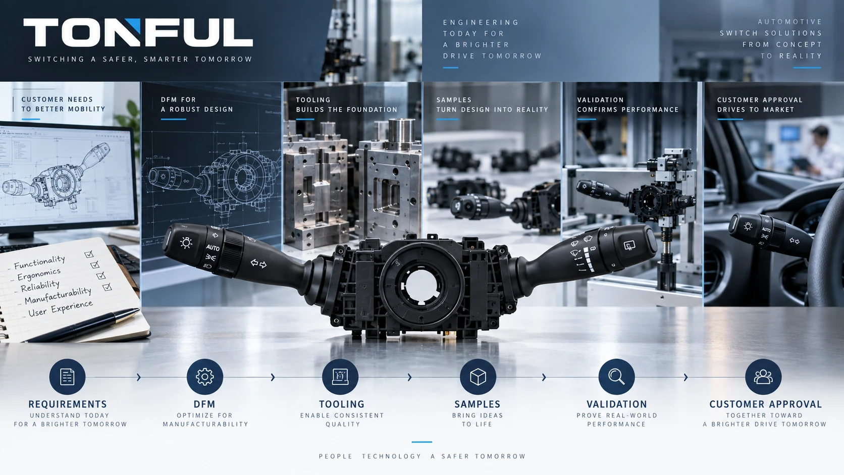
A custom combination switch project should not begin with tooling. It begins with a controlled product definition: vehicle and market, package envelope, functions, electrical architecture, human interface, environment, validation and production-volume assumptions. If these inputs remain ambiguous, tooling can freeze the wrong connector, stalk geometry or mechanism and make every later change slower and more expensive.
The development path should connect design decisions to manufacturing controls and approval evidence. DFM is not only a mold-release review; it includes stamping, plating, contact assembly, springs, lubrication, PCB/electronics, connector interfaces, poka-yoke, end-of-line testing and serviceability. PPAP may be required by the customer or contract, but it is not a universal claim that can be promised before scope and submission level are agreed.
On this page: Freeze Requirements | DFM and Tooling | Samples and Validation | Production Approval
Freeze Requirements
Build the Product Definition
Record target vehicle, market, production range, LHD/RHD, steering-column envelope and complete OE/reference chain. Define every maintained, momentary and rotary function: indicators, headlamp requests, high-beam flash, wipers, washer, cruise, horn or menu controls. Specify symbols, illumination, tactile sequence and self-cancel interface.
Define electrical architecture before connector design. A direct-load contact requires load, inrush, switching and thermal evidence; relay output needs coil/path definition; resistance-coded input needs windows and tolerances; LIN/CAN electronics require supply, network, software and diagnostics. The analog, resistive, LIN and CAN stalk guide explains the boundaries.
Create a requirements matrix with source, revision, owner, verification method and acceptance criterion. Separate customer requirements, regulations, standards, engineering choices and supplier proposals. Unknown values remain open actions; they should not be filled with generic automotive numbers.
| Requirement group | Inputs to control | Release evidence |
|---|---|---|
| Vehicle/package | Envelope, mounting, trim, steering adjustment | Interface drawing and digital/physical check |
| Human interface | Reach, symbols, detents, force-travel, return | Approved appearance and ergonomic sample |
| Functions | State matrix and option variants | Controlled function/pinout table |
| Electrical | Voltage domains, load paths, coded/network signals | Circuit and validation specification |
| Environment | Mounting-location mechanical/climatic/ingress loads | Approved test plan |
| Service/supply | OE identity, traceability, packaging, change notice | Product and logistics specification |
The RFQ and sample approval checklist provides commercial and evidence fields that should accompany this technical definition.
DFM and Tooling
Review Every Manufacturing Process
Housing DFM should cover material, wall thickness, ribs, bosses, snap fits, draft, parting lines, gates, sink/warp risk, cosmetic surfaces and mold-cavity identification. The review must preserve connector geometry, stalk clearance, sealing and dimensional stack-up after molding.
Contact-system DFM should address material, plating, stamping direction, burr control, forming, contact force, wipe, current path and wear. Spring and mechanism review should cover tolerance stack, lubrication, detent profile, return and self-cancel durability. For electronics, review PCB layout, ESD controls, soldering, programming, software revision and end-of-line access.
Assembly DFM should identify orientation errors, missing parts, wrong variants, incomplete terminal insertion and lubricant quantity. Design poka-yoke and sensor verification into the process rather than relying only on final inspection. For each critical or special characteristic, identify how it will be measured, what measurement-system evidence is needed and how the process reacts to an out-of-control result.
Control Tooling Ownership and Changes
Create a tooling register for molds, stamping dies, forming tools, assembly fixtures, programming stations and test equipment. Record owner, location, tool number, revision, cavity, maintenance, spare strategy and approval status. RFQ terms should define who owns paid tooling, what transfer rights exist and how modifications are authorized.
Tool design review should include cavity-specific dimensions, wear items, preventive maintenance, first-piece checks and change control. A “tool complete” event is not product approval. First-off parts may reveal dimensions, but production-intent evidence requires stable materials, process parameters and representative equipment.

Review the complete product and manufacturing chain before freezing molds, dies, fixtures and end-of-line tests.
Samples and Validation
Use Clear Sample Stages
| Sample stage | Purpose | Typical limitations | Approval meaning |
|---|---|---|---|
| Concept/mock-up | Package, reach and appearance | Non-functional or non-production materials | Direction only |
| Engineering sample | Circuit, mechanism and architecture learning | Prototype process/tooling | Design learning |
| Tool trial | Mold/die output and dimensions | Process not fully stabilized | Tool correction |
| Design-validation sample | Verify design against approved plan | Configuration must be defined | Design evidence |
| Production-intent sample | Production materials, tooling and process | Controlled deviations only | Production-readiness evidence |
| Approved reference | Named retained sample and documentation | Limited to approved revision/scope | Comparison standard |
Do not call an engineering sample “mass-production approved.” Label every sample with part/revision, build stage, lot, deviations and intended use. Keep golden samples protected and time/revision controlled.
Validate Design and Process Separately
Design verification may include dimensions, force-travel, state/pinout matrix, loaded voltage drop, coded/network outputs, illumination, mechanical endurance, vibration, shock, temperature, humidity, dust/water, chemicals, EMC/transients and installed-vehicle function as applicable. Test methods, quantities, severities and limits come from the approved plan.
The combination switch environmental test plan provides sample-allocation and sequence logic. The mechanical endurance guide provides cycle and failure-record controls.
Process validation asks whether manufacturing can repeatedly produce the approved design. Review process flow, PFMEA, Control Plan, work instructions, tooling, MSA, capability/SPC where applicable, error-proofing, maintenance, training, traceability, packaging and capacity evidence. Define first-piece, tool/cavity change, material change and restart controls.
Use a Deviation Register
Prototype and launch builds often contain deviations. Record each deviation, affected samples, reason, risk, owner, expiry and closure evidence. Do not mix deviated samples into qualification without explicit approval. A passing test on a hand-corrected part does not validate the uncorrected production process.

Identify each sample stage and deviation so prototype evidence is not mistaken for production approval.
Production Approval
Connect APQP, Control Plan and PPAP
AIAG’s APQP overview describes gated planning, sourcing, change management, risk mitigation and traceability. AIAG’s PPAP overview describes PPAP as the production part approval process used to demonstrate that engineering design and specification requirements are consistently met during an actual production run.
Use these only where required by the customer, contract or quality agreement. Confirm applicable manuals, customer-specific requirements, submission level and forms. Do not claim that every aftermarket project needs PPAP or that a submitted package equals customer approval.
Keep the quality chain aligned:
Customer requirements -> APQP/project plan -> design/process risks -> process flow -> PFMEA -> Control Plan -> work instructions -> inspection/test records -> PPAP or customer approval -> serial controls
Changes to one link should trigger review of downstream documents. For example, a contact-plating change affects drawing, risk, validation, incoming controls, capability and submission evidence.
Prepare a Release Matrix
| Gate | Required evidence | Decision |
|---|---|---|
| Requirements | Approved matrix and unresolved-action status | Proceed/Hold |
| Design freeze | Drawings, BOM, interfaces and risk review | Proceed/Hold |
| Tool release | DFM closure and tooling plan | Proceed/Hold |
| Tool trial | Dimensions, cavity findings and correction plan | Proceed/Hold |
| Design validation | Approved results and failure closure | Proceed/Hold |
| Process validation | Production-intent run and control evidence | Proceed/Hold |
| PPAP/customer approval | Required submission and signed status | Approved/Interim/Rejected |
| Launch | Capacity, packaging, traceability and safe-launch controls | Release/Hold |
Interim or conditional approval must define exact part/revision, plant/process, quantity or period, deviations, owner and closure. A sample approval cannot be silently expanded to another vehicle, connector, software or tooling cavity.
Before each gate closes, review unresolved technical assumptions, supplier dependencies, special characteristics, validation failures and timing risks in one controlled action list. Record the decision maker and evidence required for closure. Schedule pressure is not evidence that an open requirement is acceptable.
Commercial and Change-Control Questions
The quotation should state NRE/tooling, ownership, sample stages, validation responsibility, submission requirements, forecast/volume assumptions, packaging, lead-time basis and change-notification obligations. Values must be confirmed by the project; this guide makes no fixed TONFUL promise.
After launch, control supplier, material, tooling, cavity, process, software, test-program and location changes. Assess revalidation and resubmission before implementation. Retain approved reference samples, records and traceability for the contractually required period.
Final Approval Checklist
- Product, vehicle, function and electrical requirements are controlled.
- DFM covers molding, stamping, plating, mechanism, electronics and assembly.
- Tool ownership, revision, maintenance and cavity identity are documented.
- Sample stages and deviations are visibly identified.
- Design and process validation use production-intent configurations.
- Test plans define samples, setup, monitoring and acceptance sources.
- Process Flow, PFMEA, Control Plan and records remain aligned.
- MSA and capability/SPC evidence are included where applicable.
- PPAP scope, level and customer-specific requirements are confirmed.
- Signed approval status and change-control obligations are retained.
Work With TONFUL
Sample approval must name the design revision, tooling status and manufacturing location. A hand-built or soft-tool sample can confirm interface and function, but it does not automatically approve production-tool capability, cavity-to-cavity variation or serial controls. Define which evidence must be repeated when production-intent material, equipment or software becomes available.
Where PPAP is contractually required, agree the submission level, customer-specific forms and retained evidence before launch. An accepted package does not authorize future design, supplier, material, tooling or process changes outside the approved notification and reapproval route.
TONFUL’s automotive combination switch range provides a starting point for OEM/ODM discussions. Share the vehicle envelope, function matrix, electrical architecture, annual-volume assumptions, validation specification, tooling/commercial boundaries and customer approval requirements. TONFUL can review feasibility and sample planning against the defined project; tooling, PPAP, capacity and timing should be confirmed in a controlled quotation and project plan.