
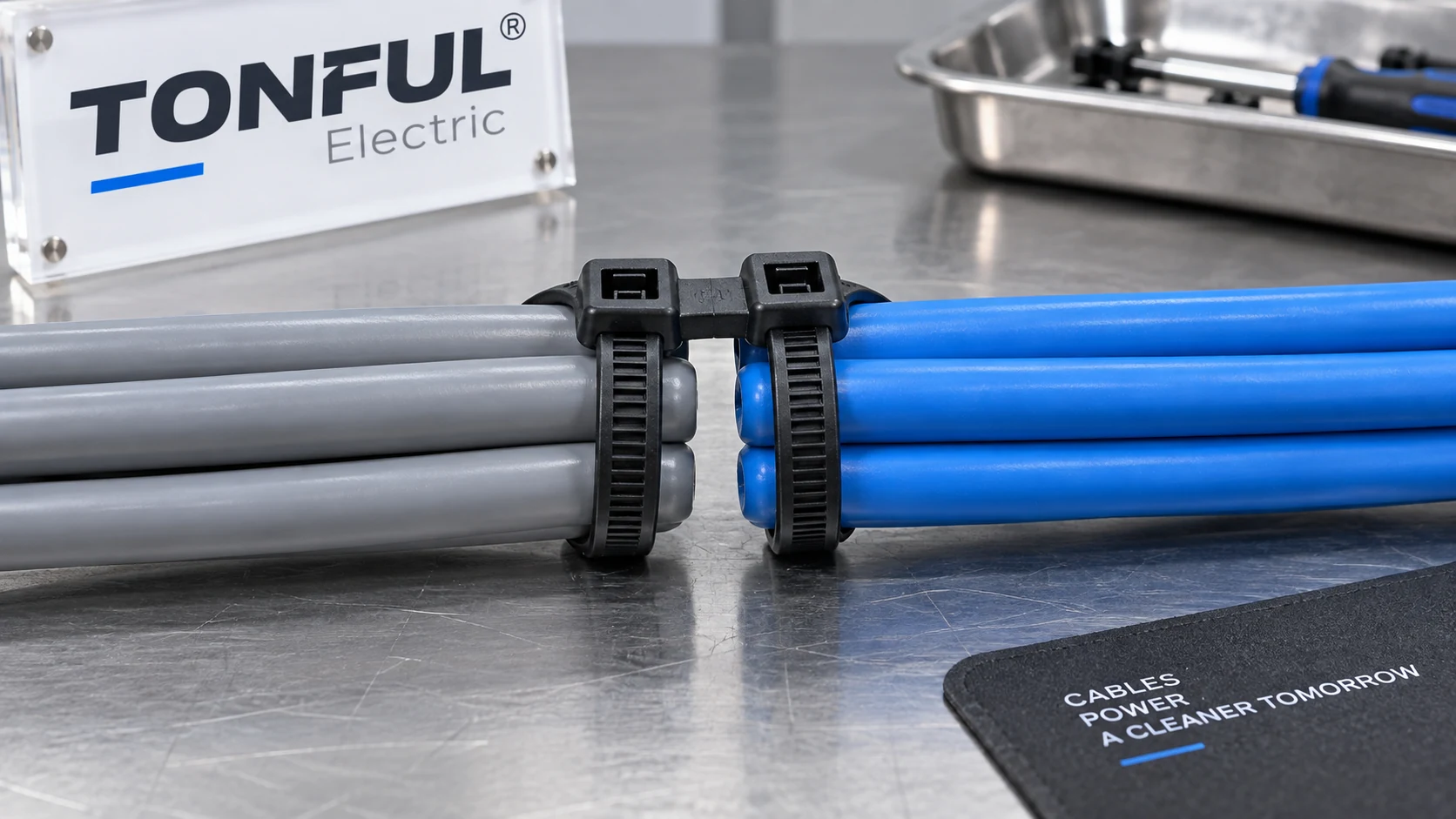
Two cable runs often need to follow the same route without becoming one compressed bundle. A double-loop cable tie can hold each run in its own loop using one purpose-designed strap and double-head arrangement. That may simplify assembly and keep the groups visually distinct, but it does not automatically create a specified electrical clearance, eliminate abrasion or carry both cable weights as a primary support.
This guide explains the actual two-loop geometry, when it is useful and how to validate it. The term double loop is sometimes used loosely for two ordinary ties linked together or one strap wrapped twice. Those are different constructions. For a purchase decision, identify the exact product drawing, head path and rated conditions before treating one design as equivalent to another.
Recognize the Two-Head, Two-Loop Construction
A purpose-made double-head tie has a strap and locking arrangement that permits two separate closed loops. One loop captures the first cable group; the second captures the parallel group. The central head geometry can hold them apart. HellermannTyton’s double-head tie example explicitly describes a dual locking head creating two loops and separation between parallel bundles. Its dimensions and strength apply to that supplier’s item, not to a TONFUL product or every double-loop design.
The HellermannTyton DH-series catalogue also notes that the two bundle diameters can differ and that a maximum bundle diameter may be stated as a combined limit. This is an important purchasing detail. Do not assume each loop can accept the catalogue maximum independently. Ask for first-loop range, second-loop range, combined range and the permitted orientation on the actual candidate drawing.
Inspect the head path on a physical sample. The tail should enter the intended opening, the teeth should engage in the specified direction and both loops should be able to tighten without partially releasing the other. A dual-head part is not proven by a photo showing two cable groups. Confirm the locking mechanism, strap length allocation and whether the head is between, beside or above the bundles after installation.
| Construction | What it actually does | Approval question |
|---|---|---|
| Purpose-made double-head tie | Forms two independent closed loops | Are both loops and head tested for this use? |
| Two ordinary ties | Each tie makes one loop | Is the combined route and spacing controlled? |
| One ordinary tie around both groups | Makes one shared loop | Are the groups allowed to touch and compress? |
| Spacer plus separate ties | Uses a defined support between groups | Is mount and spacer geometry qualified? |

Conceptual geometry only; verify the actual product’s strap path, head orientation and dimensions.
Decide Why the Two Runs Must Be Separate
The design reason matters. The two groups may need independent identification, different service schedules, separate movement, or protection from rubbing. A small visible gap can help routing, but it is not proof of compliance with a required electrical spacing or segregation rule. If the separation is safety-critical, use the applicable installation code, equipment instructions and project drawing to define the actual clearance and supporting hardware.
In a control panel, two loops may keep signal and power bundles organized for assembly. That arrangement does not by itself resolve electromagnetic compatibility or permit an otherwise prohibited shared route. In a vehicle harness, loops may keep a branch separate while allowing both to follow a bracket. Check vibration, connector strain and abrasion at the bracket. In a machine, one loop might hold a hose and the other a cable, but fluid, heat and motion compatibility must be evaluated for both materials and the tie.
The TONFUL industrial cable-tie applications guide distinguishes grouping, positioning and support functions. For two runs, state the role of each loop. If the tie is only positioning the cables, provide independent support where needed. If the tie carries weight, obtain the exact product and mounting evidence for that duty. A single dual-loop closure should not be assumed to share load evenly between loops.
Size Both Loops and the Shared Strap
Measure each bundle’s minimum and maximum outside diameter in its installed state, including sleeving, insulation, labels and manufacturing tolerance. A cable group can grow after a protective sleeve is added. The first and second loops may consume different lengths of the same strap, so a design that accommodates one large loop may leave too little tail for the other. Check usable tail length after both loops are closed, not just the nominal overall strap length.
Some product sheets state one combined maximum; others show a first-hole limit and a broader overall bundle range. Treat the supplier’s geometry as authoritative for that SKU. Do not combine the largest first-loop diameter with the largest second-loop diameter unless the drawing or test plan permits it. Model the worst-case pair of bundles and build physical samples. Record insertion path and final tail cut so another installer can repeat the result.
Strap width and head size influence pressure on the cable jackets. A narrow tie tightened aggressively may indent a soft jacket, especially after thermal cycling. A larger head can create a hard contact point near a bend. Check the minimum bend radius and allowable compression from the cable or hose manufacturer. If the groups have very different stiffness or motion, one common tie may transfer movement into the more fragile group.
| Fitment field | Required entry for Loop 1 | Required entry for Loop 2 |
|---|---|---|
| Bundle ID and material | Cable/hose type and drawing | Cable/hose type and drawing |
| Diameter range | Minimum and maximum installed OD | Minimum and maximum installed OD |
| Route movement | Vibration, flex or service motion | Vibration, flex or service motion |
| Jacket protection | Contact and compression limit | Contact and compression limit |
| Tie allocation | Strap path and tail remaining | Strap path and tail remaining |
| Verification | Retention and clearance result | Retention and clearance result |
Check the Separation Feature
The head may create a nominal gap between the two loops, but actual gap depends on bundle diameters, head orientation, strap tension and nearby supports. Define where to measure it: at the head, at midspan or at a bracket. If a minimum gap is needed, specify a measurement method with both bundles installed at their worst-case sizes and after the relevant vibration or thermal exposure.
Two cables separated at one tie can still touch between support points. Review the full route: spacing of attachment points, sag, bend transitions, panel penetrations and connector backshells. Add a rigid divider, conduit, clamp or separate path where required by the equipment design. Never claim that a double-loop tie alone provides a universal creepage, clearance or segregation value.
The loops also need access for inspection. A head buried between two dense bundles makes it hard to see whether both pawls engaged. Position the head where an inspector can confirm strap entry and tail cut without moving energized or delicate wiring. If a group will be serviced separately, consider whether cutting one loop forces replacement of the entire tie; an alternate support may reduce rework.
Select Material for the Complete Environment
Choose the tie’s material and formulation for the hottest location, UV exposure, fluids and mechanical motion encountered along the route. The two bundles may be different: a warm hose beside a cooler cable can place one side of the tie near a fluid or heat source. A black appearance alone does not prove outdoor durability. The TONFUL solar material guide gives polymer-selection context, but the finished double-head tie still needs exact-product evidence.
PA66 requires attention to finished-part condition and storage before installation. Other polymers may have lower moisture uptake but different stiffness, chemical response or head behavior. The TONFUL storage guide covers nylon handling. For washdown or marine exposure, the tie and any mount need their own wet- and chemical-service validation; two loops do not make the part waterproof.
Do not transfer a single-loop tie’s temperature or tensile declaration to a double-head version made from the same resin. The extra head, strap path and unequal loop sizes can change failure mode. Ask whether the exact double-head part was evaluated at the specified temperature and installation condition. If color or additive changes, review whether the original results still apply.
Install and Inspect Both Closures
Make a work instruction with photographs of the correct first and second loop paths. Define which bundle enters first, the position of the central head, the permitted tool and tension setting, and the required tail length or flush cut. A reversed threading sequence can leave the head rotated or the second loop short. Train operators on the actual production part, not an ordinary tie with a similar width.
Inspect both loops separately: each strap must be fully engaged, the head undamaged, the bundles held without jacket indentation, and the intended gap preserved. Confirm that the tail does not point into service access or abrade another cable. Check the tie after route movement or environmental conditioning, not only immediately after installation.
For electrical installations, UL’s cable-tie application guidance distinguishes securing from products evaluated for primary support and addresses fixing devices and markings. It does not certify a particular TONFUL double-loop part or make every two-head tie suitable for support. The exact model, package marking and approved use must be checked if a rating is required. The TONFUL tensile-strength guide explains why a loop test result is not installed working load.
Test the Installed Assembly, Not Only the Tie
A qualification plan should pair each claim with evidence. For retention, measure both loops and identify which one slips or breaks. For separation, measure the specified gap at the defined locations after installation and exposure. For environmental durability, age production-intent samples assembled on representative cable jackets and mounts. If the design uses vibration or flexing, monitor migration and contact damage, not just final tensile strength.
| Claim or risk | Test condition to define | Record and decision |
|---|---|---|
| Both loops retain bundles | Diameters, load path, tool, temperature | Loop 1/2 slip, break and head damage |
| Required spacing persists | Gap locations, motion and aging | Initial/final gap and contact evidence |
| Cable jackets remain sound | Jacket type, compression, vibration | Indentation, abrasion or cracking |
| Mount retains route | Bracket, clip, panel and substrate | Pull-out, displacement or corrosion |
| Service is repeatable | Cut/replacement procedure | Correct reinstallation and ID retention |
Set sample counts, fixture, pull rate, limits and pass/fail rules from the approved drawing, customer requirement or qualification plan. Do not publish a generic “double-loop tensile rating” as if it applies to each loop independently. Preserve failures and note whether the head, tooth, strap, cable jacket or mount failed first. If a test uses a sample from a different material grade or head revision, it cannot automatically approve the production part.

Illustrative inspection; the pictured separation is not a measured safety clearance.
RFQ and Release Checklist
Send the supplier the two bundle drawings, diameter ranges, combined envelope, cable jackets, route drawing, head orientation, minimum required gap if any, environment, service motion and intended support function. Ask for the exact double-head construction, material grade, loop-size limits, test method and production-intent samples. Do not accept a generic single-loop catalogue entry as confirmation of dual-loop supply.
Approve a sample record containing part/revision, head design, material/lot, Loop 1 and Loop 2 bundle IDs, tool setting, installed photographs, clearance measurements, retention results, failure modes, acceptance source and approver. Review the worst-case combinations, not only two average-size bundles. A tool, material, head, mount or cable-jacket change may require requalification.
TONFUL’s cable tie range is a starting point for discussing this application. Confirm whether a suitable double-head design is available and obtain controlled evidence before making a product claim. Where a single tie cannot preserve the needed gap or service independence, choose a different routing method rather than force-fitting the two-loop concept.