
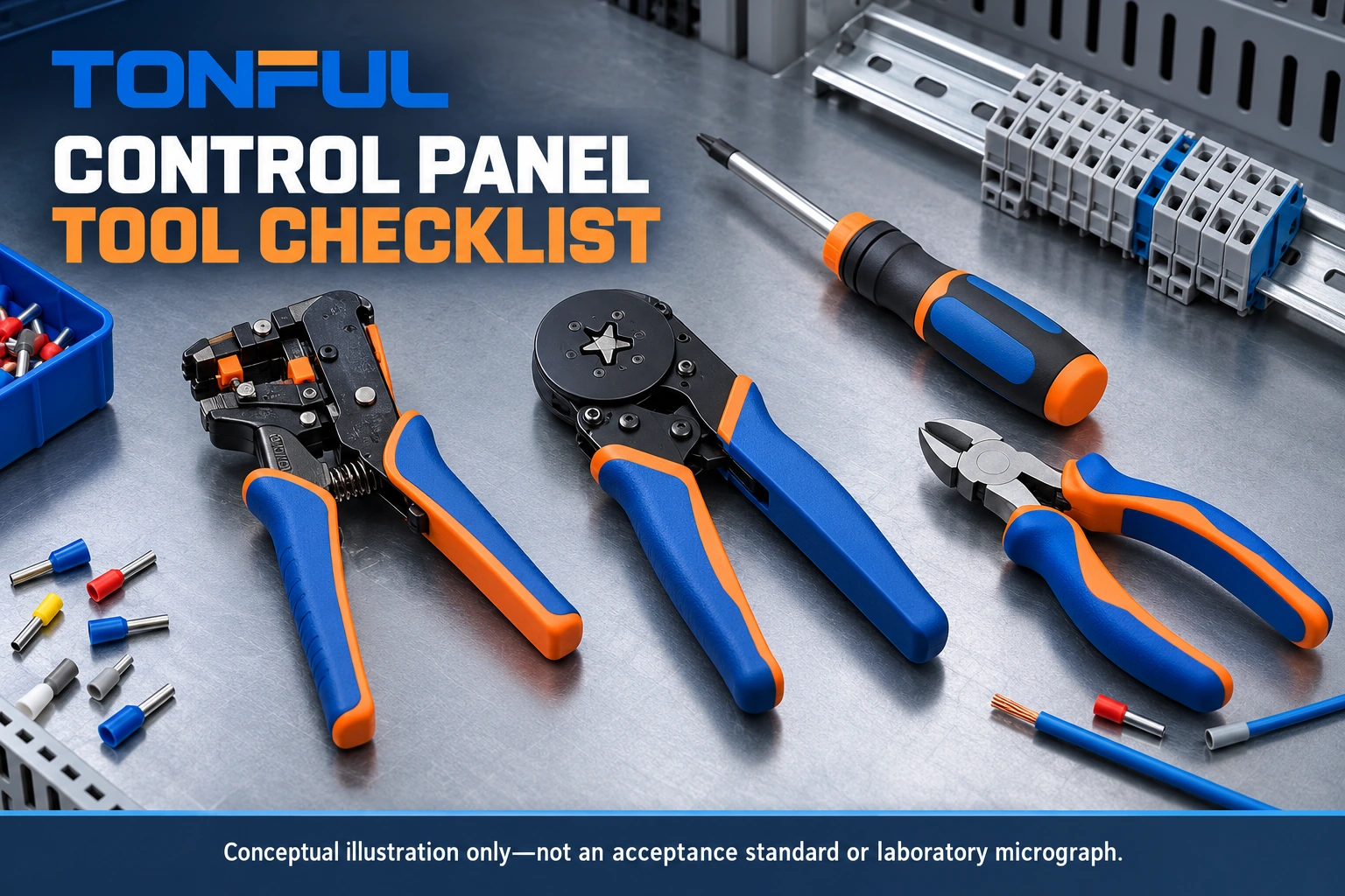
Electrical tools for control panel wiring should follow the connection schedule, not the number of pieces in a toolbox. A cutter, stripper, crimper and screwdriver perform different operations. A tool that handles one wire size is not automatically suitable for every insulation, terminal or device that uses that conductor.
Start with an approved panel drawing and bill of materials. Identify the wire construction, termination family, terminal instructions and inspection requirements. Then allocate tools to each task. This approach prevents a familiar problem: buying a complete-looking kit that cannot produce or verify the connections actually specified.
The checklist below is for qualified personnel working under an approved, deenergized-work procedure. It is a purchasing and process-planning aid, not an electrical design, energized-work method or substitute for device instructions.
Contents: Safe scope; Task matrix; Wire preparation; Termination and torque; Routing and verification; Kit release.
Set the Safe Scope Before Selecting Tools
Tool selection begins after the work boundary is defined. Identify incoming power, auxiliary supplies, stored energy and possible backfeed. A control circuit that appears inactive is not evidence that the whole enclosure is safe. The qualified person responsible for isolation must apply the applicable procedure and establish the permitted work area.
In the United States, OSHA’s electrical work-practice rule addresses deenergizing exposed parts, lockout or tagging and qualified verification of the deenergized condition. Other jurisdictions and employers may impose different or additional requirements. This checklist assumes that safe state has been established before cutting, stripping or terminating begins.
Insulated appearance is not authorization
Plastic handles do not establish an electrical protection rating. If insulated tools are required by the approved procedure, verify the exact product documentation, marking authenticity, condition and application limits. A VDE mark on an appropriate tool is not blanket permission to work live. It does not replace training, isolation, risk assessment or protective measures.
Keep damaged insulation, loose pivots and chipped cutting edges out of service. Plan blade and die maintenance separately from production. Follow the manufacturer’s isolation, battery-removal or stored-energy release instructions before accessing hazardous moving parts; do not improvise a maintenance sequence from the tool’s appearance.
Match Electrical Tools for Control Panel Wiring to Tasks
Build the tool list from the actual connection schedule. Separate wire preparation, crimp formation, terminal operation and inspection. TONFUL’s electrical tools range provides a starting point for sourcing discussions, but category membership alone does not confirm a specific tool-to-connection match.
| Task | Tool or equipment to evaluate | Evidence required before release | Stop condition |
|---|---|---|---|
| Cut wire or cable | Cutter approved for the conductor construction | Material and construction compatibility; clean trial cut | Crushing, strand displacement or unsupported material |
| Remove insulation | Stripper matched to wire and insulation | Strip-length instruction; representative trial samples | Nicks, missing strands or insulation damage |
| Crimp ferrules | Ferrule-specific crimper | Ferrule, conductor, profile and terminal compatibility | Unsupported ferrule or incomplete insertion |
| Crimp other terminals | Correct terminal tool and die | Terminal application instruction and approved verification | Wrong cavity, terminal family or wire construction |
| Tighten screw terminals | Suitable controlled torque tool and bit | Device torque instruction; tool verification status | Missing instruction, damaged screw or poor access |
| Operate spring terminals | Specified actuator or screwdriver where required | Device connection instructions | Tool damages spring opening or housing |
| Identify and route conductors | Label equipment and suitable tie tooling | Drawing identification and routing requirements | Unreadable labels, crushed insulation or sharp tails |
Add columns for tool ID, workstation, responsible owner and document revision when copying this matrix into a shop record. An unresolved compatibility cell means the connection is not ready for release, even if the rest of the kit is available.
Avoid a universal wire schedule
There is no universal control-panel wire color or conductor size that this checklist can supply. Use the applicable project standard, destination requirements, approved design and device limits. Record both conductor area and construction where relevant; a nominal size alone does not describe strand arrangement or insulation behavior.
Separate the approved design from purchasing convenience. Changing conductor size to suit an available tool can affect device compatibility, routing and electrical design. Escalate that change to engineering rather than treating it as a shop-floor substitution.
Control Cutting and Stripping as Separate Operations
A clean cut gives the stripper a predictable starting condition. Evaluate the actual cable or wire, not a convenient substitute from the sample drawer. Check whether the selected cutter supports the conductor material and construction. A copper or aluminum cutting application does not establish suitability for steel reinforcement, ACSR, armor or energized conductors.
Consider access as well as cutting capacity. A bulky head may be acceptable on the bench but awkward near a duct or terminal rail. Plan preparation outside the enclosure where practical, retain identification and manage offcuts so they cannot remain inside equipment.
Qualify the strip on representative wire
The stripper removes insulation; it does not establish the final crimp or terminal compatibility. Compare candidate wire stripping tools against the wire types in the job and request model-specific documentation. Self-adjustment is a mechanism, not proof that every insulation wall or material will process correctly.
Record the required strip length from the connection instructions. Inspect the full exposed circumference for damaged strands, scoring, pulled insulation and remaining fragments. If a defect appears, contain the affected work and check wire identity, blade condition and setup before continuing. Repeatedly increasing pressure without identifying the cause can turn a setup problem into conductor damage.
Use an engineering-approved trial and sampling plan. Define which changes require another check, such as a new wire lot, replacement blade, different insulation or altered setup. Do not create a universal acceptance limit from a magnified conceptual illustration; the controlling documents must define acceptable workmanship.

Separate Ferrule Crimping, Terminal Crimping and Torque
A ferrule contains prepared strands in a tubular end termination. It is not interchangeable with a ring terminal, fork terminal or open-barrel contact. These constructions need different tooling and application evidence. The panel termination selection guide addresses that separate connection-choice decision. TONFUL’s crimping tools selection page distinguishes ferrule, terminal and other tool families; use that distinction when preparing the RFQ.
Check the ferrule’s conductor compatibility, sleeve dimensions, insertion depth and finished profile against the receiving terminal’s instructions. TONFUL’s cord end terminal range can help identify the product family for enquiry. It does not establish approval for every device or every combination of wires.
Ferrules are conditional, not mandatory everywhere
Some terminal designs accept specified bare conductors; others permit or call for particular ferrule arrangements. Follow the device instruction rather than assuming all stranded conductors require ferrules. A twin ferrule is not permission to place two conductors into a terminal that does not allow that arrangement. Do not fold, double or trim conductors merely to make them fit an available ferrule.
For non-ferrule terminals, identify the terminal part number, wire construction, application tool and die or cavity. A ratchet completing its cycle does not demonstrate an acceptable connection. The approved inspection or test plan must establish what evidence is required for that termination, with acceptance criteria taken from the governing documents.
Torque belongs to the receiving device
Use the device manufacturer’s tightening instruction for the exact terminal and conductor arrangement. Do not infer torque from screw diameter, copy a neighboring device’s value or create one shop-wide setting. Confirm units, bit geometry, access and whether the selected torque tool operates appropriately within its documented range.
A torque screwdriver tightens the connection; it is not a substitute for crimp tooling. Conversely, a good crimp does not demonstrate correct terminal tightening. Record the setting source and tool identity. Follow the quality system for verification and calibration, and the device instructions for any permitted rechecking. Repeated tightening by feel can damage a connection rather than improve it.
Route, Identify and Verify Without Hiding Defects
Routing tools should preserve the electrical and mechanical intent of the drawing. Labels need to remain readable after installation and correspond to the approved wire schedule. Allow specified bend space and service access. A tightly dressed bundle is not automatically a better bundle if it strains terminations or obstructs inspection.
For cable ties, evaluate the tie material, width, thickness, head geometry and tool compatibility together. Set tension through the approved trial process rather than selecting a value for appearance alone. Check for insulation compression and sharp cutoff tails. A cable-tie tool cannot correct an unsuitable routing design.
Keep inspection visible before final dressing closes the area. Check conductor identity, terminal position, strand containment, insertion and label agreement. A wire that reaches the correct terminal can still have a damaged conductor or unsupported termination, so continuity alone is not a complete workmanship decision.
Keep electrical testing inside its own approved plan
Use suitable test equipment and qualified procedures for the test being performed. Do not apply resistance or continuity testing to an energized circuit. Do not energize unknown pins to discover where they go. Connected electronics may need specific isolation or test arrangements; follow the approved design and equipment instructions before any electrical test.
Distinguish the record of deenergized-state verification from the production inspection record. They serve different purposes. Test instruments, torque tools and crimp tools also need different control methods. A calibration sticker on one item does not qualify the rest of the workstation.

Release a Controlled Kit, Not Just a Toolbox
Before ordering, give each proposed tool a defined job and acceptance source. Keep the tool list linked to the panel revision so a component change triggers a tooling review. Identify shared tools that could become bottlenecks and decide whether backup tooling needs the same qualification before it can replace the primary tool.
| Release field | Entry to complete |
|---|---|
| Panel and drawing revision | Approved document reference |
| Connection family | Wire, terminal and receiving-device identity |
| Preparation setup | Cutter, stripper, blade and strip-length source |
| Crimp setup | Tool, die or cavity, ferrule or terminal instruction |
| Terminal operation | Torque or spring-actuation instruction and tool |
| Verification | Inspection or test plan, result and evidence reference |
| Maintenance | Wear-part identity, service instruction and owner |
| Approval | Reviewer, date and unresolved restrictions |
For a repeat build, review what changed rather than copying the previous release automatically. A new terminal supplier, ferrule sleeve length, wire insulation or screwdriver bit can alter the operation. Quarantine unapproved substitutions and keep trial samples distinct from production stock. Where evidence is missing, leave the affected operation on hold instead of signing a general kit approval.
The useful purchasing outcome is a documented match between tasks and tools, with clear limits and an owner for every open question. Send TONFUL the connection schedule, representative wire and terminal details, required tool functions and approval-record needs. Ask for model-specific recommendations and supporting documents before confirming the control-panel wiring kit.