
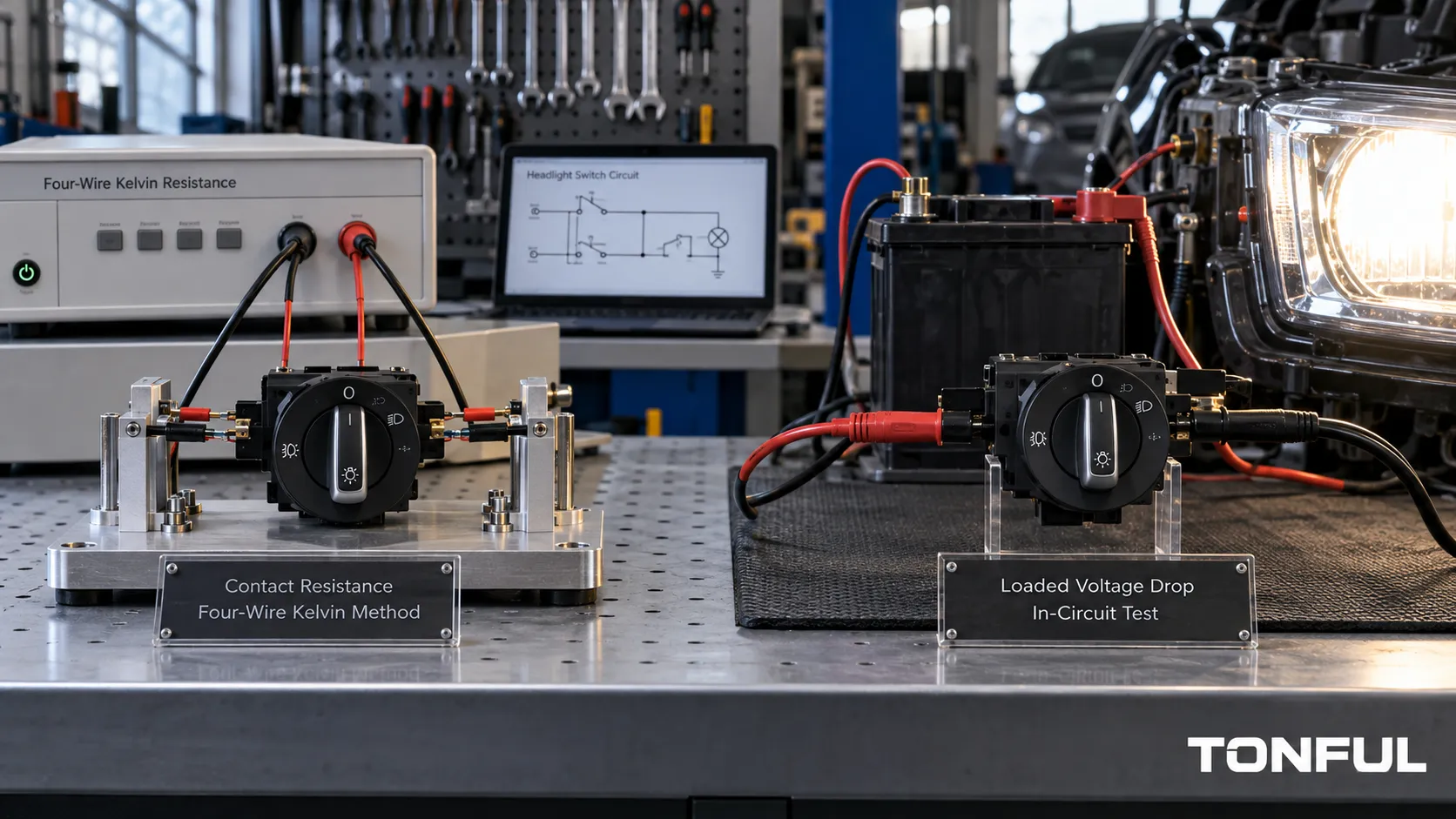
Contact resistance and voltage drop describe related but different evidence. A controlled low-resistance measurement can characterize an isolated switch contact path, while a loaded voltage-drop test can locate loss across an operating vehicle circuit. Neither method should be reduced to a continuity beep, and neither has a universal pass value for every headlight switch architecture.
TONFUL’s current headlight-switch range presents vehicle applications and OE references. Confirm the exact vehicle, complete OE reference, connector, pinout, functions, approved sample and project-specific validation plan before ordering or testing.
Quick Evidence Matrix

Conceptual illustration only – not a vehicle procedure, laboratory result, universal limit, or acceptance standard.
| Work area | Required focus | Acceptance source |
|---|---|---|
| Choose the Method From the Architecture | Use the wiring diagram to identify direct-load contacts, relay commands, switched grounds, coded resistances and BCM inputs. | Project specification, approved plan, or root-cause evidence |
| Prepare the Sample and Instrument | Record sample quantity, part and lot, conditioning, connector and cavity orientation, switch position, meter range, resolution and accuracy, lead condition, fixture and ambient temperature. | Project specification, approved plan, or root-cause evidence |
| Measure Low Contact Resistance Correctly | Define test current, source polarity, forward/reverse measurement or offset compensation, Force and Sense locations, stabilization time and lead subtraction. | Project specification, approved plan, or root-cause evidence |
| Perform a Loaded Voltage-Drop Test | Operate the circuit under the vehicle-specified load and conditions. | Project specification, approved plan, or root-cause evidence |
| Interpret Resistance, Heat and Instability | A stable reading outside the specified limit, intermittent open, position-sensitive change or increasing drop can indicate contact wear, contamination, reduced terminal force, damaged crimps or connector heat. | Project specification, approved plan, or root-cause evidence |
| Define Acceptance and Retest Rules | Use limits from the approved drawing, product specification, customer plan or vehicle procedure. | Project specification, approved plan, or root-cause evidence |
The matrix defines evidence categories, not pass values. Unknown requirements must remain open until the document owner confirms them.
For every section below, identify the applicable component, circuit path and sample, then retain objective evidence. Any numeric requirement must cite the product drawing, OEM or customer specification, qualification plan or approved test procedure. This common rule is stated once here; each technical section adds records specific to its measurement risk.
Choose the Method From the Architecture
Use the wiring diagram to identify direct-load contacts, relay commands, switched grounds, coded resistances and BCM inputs. Contact-resistance testing may suit an isolated mechanical path; voltage drop may suit an energized load path. Networked or module-interpreted states can also require scan data.
Draw the exact upstream and downstream boundaries around the path being evaluated. A switch-only Kelvin result cannot be compared directly with a vehicle voltage-drop result that also includes terminals, wiring, relay contacts or grounds. Record the circuit revision, energized state and any module command or scan-data condition needed to reproduce the state.
Prepare the Sample and Instrument
Record sample quantity, part and lot, conditioning, connector and cavity orientation, switch position, meter range, resolution and accuracy, lead condition, fixture and ambient temperature. Never use resistance mode on a powered circuit. Protect terminals with correct probes or a breakout harness.
Warm up and zero the instrument as its manufacturer specifies. Record model, serial number, measurement range, resolution, stated accuracy, calibration status, lead set and fixture identity. Before connecting, confirm the circuit is de-energized for resistance mode and inspect probes for damaged insulation, loose tips or contamination that could change contact stability.
Measure Low Contact Resistance Correctly
Define test current, source polarity, forward/reverse measurement or offset compensation, Force and Sense locations, stabilization time and any approved reference-wire correction. A four-wire Kelvin method minimizes the effect of current-lead resistance, but every resistance located between the two Sense points remains part of the reported result. This may include switch contacts, internal conductors, fixture interfaces, terminals or wire, depending on probe placement.
Connect Force HI and Force LO so the instrument drives current through the chosen path. Place Sense HI and Sense LO at the two boundaries whose voltage difference defines the reported resistance. Keep the Sense connections inside the Force connections and as close as practical to the intended boundaries. Photograph or diagram all four locations; moving a Sense point changes the measurand.
Low-level readings can be influenced by thermoelectric EMF from dissimilar metals and temperature gradients. When the approved instrument and method support it, current reversal uses equal-magnitude positive and negative currents to estimate resistance while cancelling a stable offset. Offset-compensated ohms can compare readings with current applied and removed. Neither technique should be selected after seeing an unfavorable result, and neither is valid if switching speed, settling or thermal drift violates the instrument procedure.
Test current also dissipates power in the measured path. Excessive self-heating can change contact or conductor resistance during the reading. Record current, pulse or dwell behavior and temperature; select them from the controlled method and verify that the measurement itself is not driving the observed change.
Perform a Loaded Voltage-Drop Test
Operate the circuit under the vehicle-specified load and conditions. Measure across the selected path rather than only from a point to ground. Separate power-side and ground-side drops, record battery voltage and load, and move through the circuit to localize loss.
Record battery voltage, operating current, lamp or simulated load, switch command, engine or charging state where relevant, and both probe locations. Test the circuit under the condition that produces the complaint. A no-load reading may appear normal even when resistance causes substantial loss under operating current.
Interpret Resistance, Heat and Instability
A stable reading outside the specified limit, intermittent open, position-sensitive change or increasing drop can indicate contact wear, contamination, reduced terminal force, damaged crimps or connector heat. Compare switch-only evidence with mating connector, relay, wiring, grounds and lamp-side findings.
Correlate the electrical result with temperature, terminal retention, connector discoloration, harness movement and the exact switch position. Repeatability across controlled operations is useful evidence, but repeatedly cycling a damaged connector can temporarily restore pressure and erase the original symptom. Preserve photographs and first-failure readings before disconnecting the interface.
Define Acceptance and Retest Rules
Use limits from the approved drawing, product specification, customer plan or vehicle procedure. State sample quantity, invalid-test rules and retest authorization before testing. Preserve initial and aged values, change from baseline, failure mode and disposition; do not average away an intermittent failure.
Define how open readings, unstable readings, range overload, instrument faults and disturbed probes are handled. Retesting requires documented authorization and must not replace the original result. Report every sample individually with raw value, corrected value when permitted, initial-to-aged change, failure mode, source clause and disposition.
Test or Investigation Record

This conceptual record layout supports traceability; it does not replace the controlled test or investigation form.
Use a two-column record that remains readable on mobile screens and can be copied into a laboratory form:
| Record field | Required entry |
|---|---|
| Sample identity | Part number, revision, manufacturing lot, sample ID and conditioning status |
| Circuit path | Exact upstream and downstream boundaries, switch position and included interfaces |
| Instrument | Model, serial number, range, resolution, accuracy, calibration status and fixture |
| Kelvin setup | Force HI/LO and Sense HI/LO locations, lead set and connection diagram reference |
| Test condition | Current or operating load, polarity or compensation method, settling time and temperature |
| Wire reference | Conductor construction, material, gauge, length and subtraction method when approved |
| Results | Raw value, permitted corrected value, initial value, aged value and change from baseline |
| Abnormal event | First unstable or open reading, symptom, test state and preserved evidence |
| Decision | Acceptance-source document and clause, pass/fail, reviewer and date |
For example, “Kelvin setup: Force at fixture posts; Sense at switch terminals; diagram K-04” is auditable, while “four-wire test” is not. Define sample quantity, conditioning, invalid-test rules, retest authority and data retention before execution. Preserve raw readings and photographs because a summary pass/fail field cannot replace the evidence.
Illustrative Voltage-Drop Calculation
Suppose a defined loaded path has a measured drop of 0.12 V while the measured test current is 8 A. Applying Ohm’s law to that same path:
Equivalent path resistance = V ÷ I = 0.12 V ÷ 8 A = 0.015 Ω = 15 mΩ
This example is illustrative only, not an acceptance limit. The calculated 15 mΩ belongs to everything between the voltage probes under that operating condition; it is not automatically the resistance of the switch contacts alone. Temperature, current stability, probe position and included connector or wire resistance affect interpretation. Compare the result only with a requirement that defines the same boundaries and conditions.
Fluke’s automotive electrical troubleshooting guide explains loaded voltage-drop principles. Use it for the in-circuit measurement approach, not as a source of vehicle-specific limits or pinouts. The Tektronix/Keithley Low Level Measurements Handbook explains four-wire low-resistance connections, thermoelectric EMF, current reversal, offset-compensated measurements and device-heating effects. Use the selected instrument’s controlled procedure and project requirements to define the actual setup.
Sourcing and Release Controls
Internal Links and Decision Path
- TONFUL Headlight Switch Manufacturer
- Headlight Switch, Relay or BCM Control Guide
- Headlight Switch Multimeter Test
- Bad Headlight Switch Symptoms
- Headlight Switch Buying Guide
Use the architecture guide before choosing test points, the multimeter guide for safe field measurements, the symptoms guide for fault routing, and the buying guide for fitment evidence. These pages support different decisions and should not be treated as interchangeable procedures.
Supplier and Change Control
For an RFQ or validation request, provide vehicle, market, production range, OE chain, connector views, mounting, terminal population, function matrix, architecture, load or signal definition, environment, sample quantity, test plan, acceptance sources, annual demand, packaging and traceability needs. Request controlled drawings, raw-data references, nonconformance handling and change notification.
Receiving inspection should compare labels, lot identity, housing, connector, terminals, functions and packaging with the approved sample. Define reaction plans for discrepancies. Changes to contacts, plating, terminals, springs, resistor networks, electronics, LEDs, housing, tooling, process, sub-suppliers or manufacturing site may require notice and reapproval.
Final Release Checklist
- Scope, application, part revision, sample quantity and lot are identified.
- Electrical architecture, functions, loads, environment and conditions are documented.
- Equipment, fixtures, probes, ranges, accuracy and calibration status are recorded.
- Actual results, failure modes, photographs and raw-data references are retained.
- Every limit points to an approved source; no universal value is invented.
- Invalid tests, retests, deviations and unresolved items have documented disposition.
- Approved sample, receiving controls, traceability and change notification are defined.
- Release identifies reviewer, date, approved scope and closure evidence.
Measurement Planning and Evidence Review
Before Measurement
Hold a cross-functional review with design, quality, test, manufacturing and customer representatives where required. Confirm that the fixture does not change the intended loading, every channel is represented, safety controls are adequate, software and data acquisition are versioned, and the planned evidence can support the release decision. Resolve conflicting documents before testing rather than selecting the most convenient requirement.
After Measurement
An independent reviewer should be able to reconstruct the decision from sample identity, setup photographs, calibration status, raw readings, event logs, environmental records and acceptance sources. Separate observed symptoms from confirmed causes. Open items need an owner, due date, affected-stock decision and closure evidence; conditional approval must state its exact scope.
Probe Boundaries and Reference Length
Resistance results are comparable only when the measured path is the same. Mark Force and Sense locations on the fixture drawing for a Kelvin test. For a vehicle voltage-drop test, identify the exact upstream and downstream probe points, switch state and loaded branch. Moving a probe from a terminal interface to a wire conductor changes the included resistance and can change the conclusion.
Record ambient and conductor temperature for every precision resistance result because copper resistance and contact behavior can change with temperature.
When wire is included in a bench path, record conductor construction, gauge, material, temperature and reference length. If the approved method requires subtraction of an equal-length reference-wire resistance, retain both raw and corrected values. For aging studies, report initial value, post-conditioning value and change, not only the final reading. Offset compensation or forward/reverse measurement must follow the approved method and should never be introduced selectively after an unexpected result.
If electrical evidence conflicts with heat damage or intermittent symptoms, inspect terminal retention, mating surfaces, crimps and harness movement before declaring the switch acceptable. Cross-section or teardown may be required by the investigation plan. Preserve the original connector condition because disconnecting and reconnecting can temporarily restore contact pressure.
Work With TONFUL
Send TONFUL the complete application and evidence package rather than only a switch photograph or symptom. TONFUL can compare the request with current headlight-switch applications and OE references, then align sample review and project-specific validation requirements. Final approval remains tied to controlled documentation, agreed tests and the approved sample.