
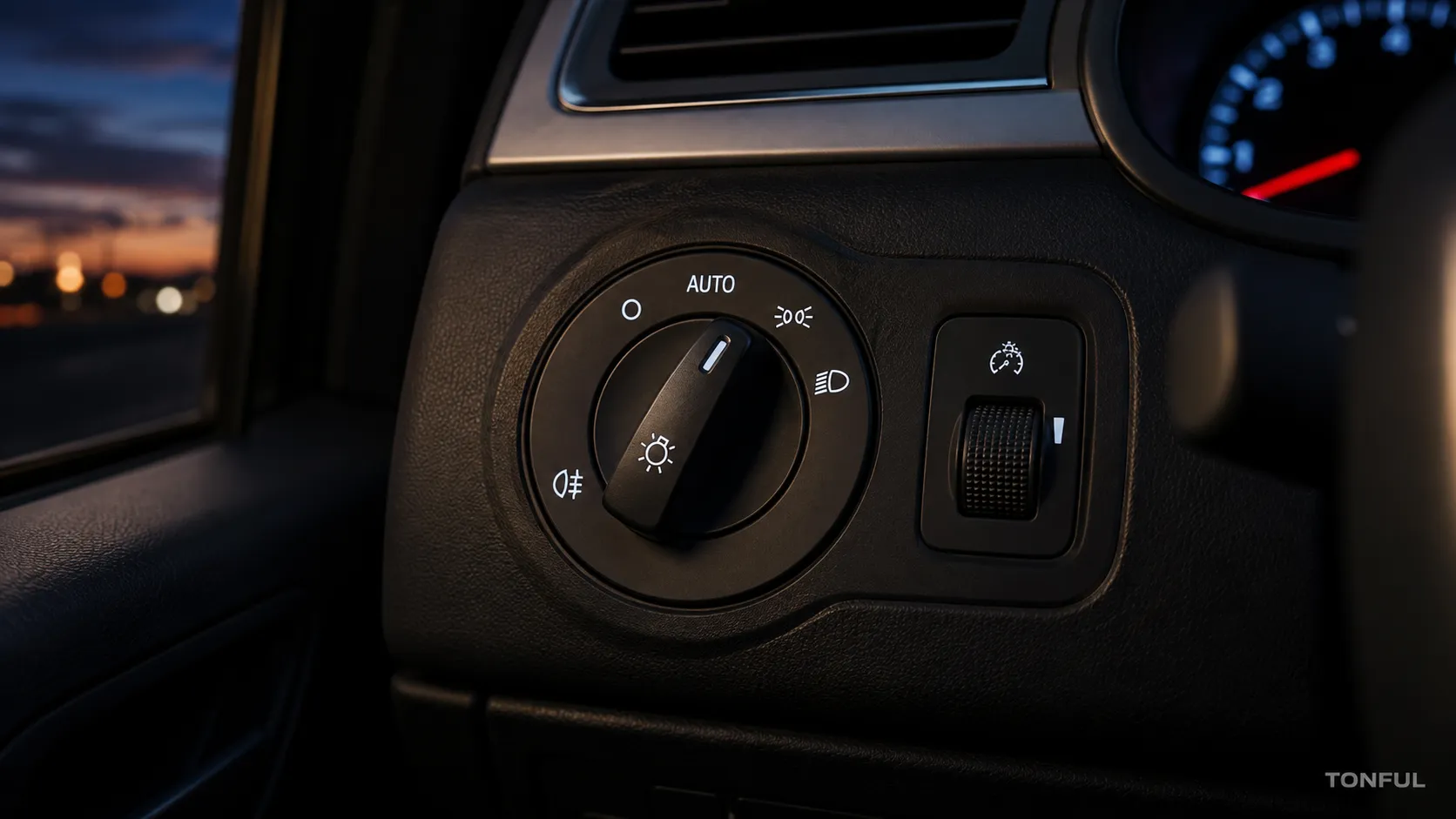
Headlight-switch symbols describe driver requests, not necessarily direct electrical outputs. AUTO may ask a BCM to evaluate an ambient-light sensor; the parking position may activate several exterior and interior circuits; a fog control can be conditional on another lighting mode; and a dash dimmer may send a resistance or momentary input rather than vary lamp current directly. Understanding those boundaries prevents incorrect fitment and diagnosis.
TONFUL’s current headlight-switch range presents vehicle applications and OE reference numbers. Confirm the exact vehicle, OE chain, connector, pinout, functions, approved sample, and project-specific validation plan before ordering. Product appearance and a shortened cross-reference are not sufficient approval evidence.
At-a-Glance Decision Table

Conceptual illustration only – not a vehicle-specific wiring diagram, fitment record, laboratory result, or acceptance standard.
| Decision area | What it means | What to verify |
|---|---|---|
| OFF and Manual Headlamp Positions | OFF may disable a manual request without disabling every regulated, safety, welcome, or daytime-running function. | Verify the physical detent against switch output or scan state and then confirm downstream response. |
| AUTO: Sensor Input Plus Module Logic | AUTO normally makes the switch one input in a larger decision. | Compare switch position with BCM data, sensor data, enabling conditions, and commanded outputs. |
| Parking Lamps: More Than Front Marker Lights | The parking request can involve front position lamps, tail lamps, side markers, license lamps, panel backlighting, and switch illumination, subject to market and vehicle design. | Separate shared command failure from local fuse, branch, connector, ground, or lamp failure. |
| Front and Rear Fog Controls | Fog controls may use a pull action, push button, rotary position, stalk ring, or separate switch. | Confirm front versus rear fog symbols, prerequisites, telltale response, module state, relay or driver output, and market configuration. |
| Dash Dimmer and Switch Illumination | A dash dimmer may be a variable resistor, resistor ladder, encoder, or pair of momentary buttons. | Verify dimmer direction, steps, minimum behavior, daytime/nighttime conditions, supply, ground, and interpreted module value. |
| Build a Function Matrix Before Ordering | A complete matrix lists every position and action, expected input, module interpretation, output response, symbol, telltale, dependency, and acceptance source. | Pair the matrix with vehicle, market, production range, full OE chain, connector orientation, pinout source, mounting dimensions, approved sample, and validation plan. |
Use the table to identify missing evidence, not to create universal pinouts or ratings. The controlling source is the applicable vehicle information, product drawing, customer specification, or approved validation plan.
OFF and Manual Headlamp Positions
OFF may disable a manual request without disabling every regulated, safety, welcome, or daytime-running function. The headlamp position can close a load contact, ground a signal, change resistance, or send a module request depending on architecture.
Verify the physical detent against switch output or scan state and then confirm downstream response. Do not declare the switch faulty when module logic intentionally keeps or turns on a lighting function.
AUTO: Sensor Input Plus Module Logic
AUTO normally makes the switch one input in a larger decision. Ambient-light data, ignition state, wipers, vehicle configuration, delay logic, camera functions, and DTCs may affect the final command.
Compare switch position with BCM data, sensor data, enabling conditions, and commanded outputs. A correct AUTO switch state with an implausible sensor value points away from the switch.
Parking Lamps: More Than Front Marker Lights
The parking request can involve front position lamps, tail lamps, side markers, license lamps, panel backlighting, and switch illumination, subject to market and vehicle design. One failed lamp does not prove a failed parking contact.
Separate shared command failure from local fuse, branch, connector, ground, or lamp failure. Record which lamps and interior illumination respond in each key state.
Front and Rear Fog Controls
Fog controls may use a pull action, push button, rotary position, stalk ring, or separate switch. Some systems require parking or low beam, inhibit fog lamps with high beam, or use momentary requests remembered by a module.
Confirm front versus rear fog symbols, prerequisites, telltale response, module state, relay or driver output, and market configuration. Do not add or promise fog functionality from appearance alone.
Dash Dimmer and Switch Illumination
A dash dimmer may be a variable resistor, resistor ladder, encoder, or pair of momentary buttons. The BCM or cluster can generate pulse-width-modulated outputs for backlighting. Switch illumination and a fog telltale may use separate circuits.
Verify dimmer direction, steps, minimum behavior, daytime/nighttime conditions, supply, ground, and interpreted module value. Test every illuminated symbol and indicator after installation.
Build a Function Matrix Before Ordering
A complete matrix lists every position and action, expected input, module interpretation, output response, symbol, telltale, dependency, and acceptance source. This exposes differences hidden by an identical bezel or connector shell.
Pair the matrix with vehicle, market, production range, full OE chain, connector orientation, pinout source, mounting dimensions, approved sample, and validation plan. Unknown functions must remain unapproved rather than being copied from a similar model.
Verification and Test Records

This conceptual evidence workflow supports documentation; it does not replace an approved vehicle procedure or product specification.
Before electrical testing, identify whether each circuit is powered, isolated, direct-load, relay-controlled, ground-side, resistance-coded, or module interpreted. Use protected probes or an approved breakout harness. Never measure resistance on an energized circuit, force an unknown module pin, or use a continuity beep as a universal low-resistance acceptance test.
A usable record includes sample ID, vehicle and market, OE reference, connector and cavity, function, switch state, supply or reference, load, meter mode and range, lead compensation where applicable, probe points, ambient condition, expected result and source, actual result, pass/fail, inspector, and date. If documents conflict, quarantine the decision until the source owner resolves the discrepancy.
Do not replace actual values with only “works” or “continuity.” If a result is unstable, preserve the measured range and the condition that produced it. Retesting is valid only after documenting why the first result was invalid or what corrective action changed the sample.
Test every supported action as a separate row in the function matrix. For OFF, AUTO, parking, manual headlamps, front fog, rear fog, dimmer increase, dimmer decrease, switch illumination, and telltales where equipped, record the physical action, switch output or scan state, required enabling conditions, commanded response, observed lamps or backlighting, and acceptance source. Include ignition state, ambient-light condition, market configuration, and dependent switch positions when they affect the result. If one function is not fitted, mark it Not Applicable with the supporting application record rather than leaving the field blank. This prevents an untested option from being interpreted as approved.
The official eCFR 49 CFR Section 571.108 establishes vehicle lighting-system requirements. It does not prove a standalone switch’s fitment, pinout, architecture, rating, or compliance for a particular vehicle.
Supplier Questions and Application Release
Use these related TONFUL resources during selection and validation:
- TONFUL Headlight Switch Manufacturer
- Headlight Switch Buying Guide
- Bad Headlight Switch Symptoms and Diagnosis
- Headlight Switch Multimeter Test
- Headlight Switch, Relay or BCM Control Guide
For an RFQ, provide the vehicle, market, production range, full OE number and suffix, installed location, front and connector-end photographs, dimensions, connector orientation, terminal population, symbols, functions, electrical architecture, annual demand, packaging, and required validation. Confirm whether supplied scope is the headlight switch alone; do not assume relays, BCMs, sensors, lamp assemblies, or unrelated controls are included.
Request controlled drawings, function matrices, sample records, inspection and test reports, packaging approval, lot traceability, nonconformance handling, and change notification. Define which changes to contacts, terminals, resistor networks, electronics, LEDs, housing materials, tooling, process, software where applicable, sub-supplier, or manufacturing site require notice and reapproval.
Receiving Inspection and Catalog Control
Receiving inspection should compare label and lot identity, housing, keying, connector face, terminal population, mounting features, symbols, detents, illumination, and packaging with the approved sample. Sampling level and reaction plan must come from the purchase agreement or quality plan rather than an invented universal rule.
Keep catalog application data revision-controlled. When an OE number is superseded, record direction and conditions instead of treating both numbers as automatically interchangeable. Suspect stock should remain segregated until fitment and function evidence closes the discrepancy.
Questions for the Supplier
Ask which drawing revision defines the supplied part, which vehicle applications and OE references are currently supported, what functions are included, which connector view controls cavity numbering, and which validation records can be provided. Confirm whether electronics, illumination, resistors, contacts, terminals, and housing materials are controlled by specification.
Also define packaging, labels, traceability, nonconformance communication, and change notification before purchase. A technically correct sample can still create receiving or service problems when its label, packaging, or application record is ambiguous.
Application Release Boundaries
Publish only the application scope supported by the evidence. Record market, production dates, trim or option conditions, left- or right-hand-drive configuration where relevant, and any excluded functions. A shared model name does not prove that connector, architecture, symbols, illumination, or software interpretation stayed constant across revisions.
When evidence supports a sample but not the full production range, label the application as pending rather than broadening it by inference. Recheck the approved scope after an OE supersession, supplier change, connector revision, or new vehicle option. This keeps the catalog, quotation, incoming inspection, and customer approval aligned to the same controlled definition.
Final Approval Checklist
- Vehicle, market, production range, OE chain, and installed location are recorded.
- Switch type, symbols, mounting, connector keying, terminal population, and orientation match.
- Every function and dependency appears in a controlled function matrix.
- Electrical architecture and test reference are identified before probing.
- Measurements include conditions, actual values, units, test points, and acceptance source.
- The mating connector, wiring, grounds, related modules, relays, and loads are considered where relevant.
- No universal pinout, rating, compatibility, certification, or durability claim is made without evidence.
- Approved sample, packaging, traceability, and change-notification responsibilities are documented.
Work With TONFUL
Send TONFUL the complete application package rather than only a switch photograph. TONFUL can compare the request with current headlight-switch applications and OE references, then align sample review and project-specific validation requirements. Final release should remain tied to the approved sample, controlled documentation, and agreed commercial scope.