
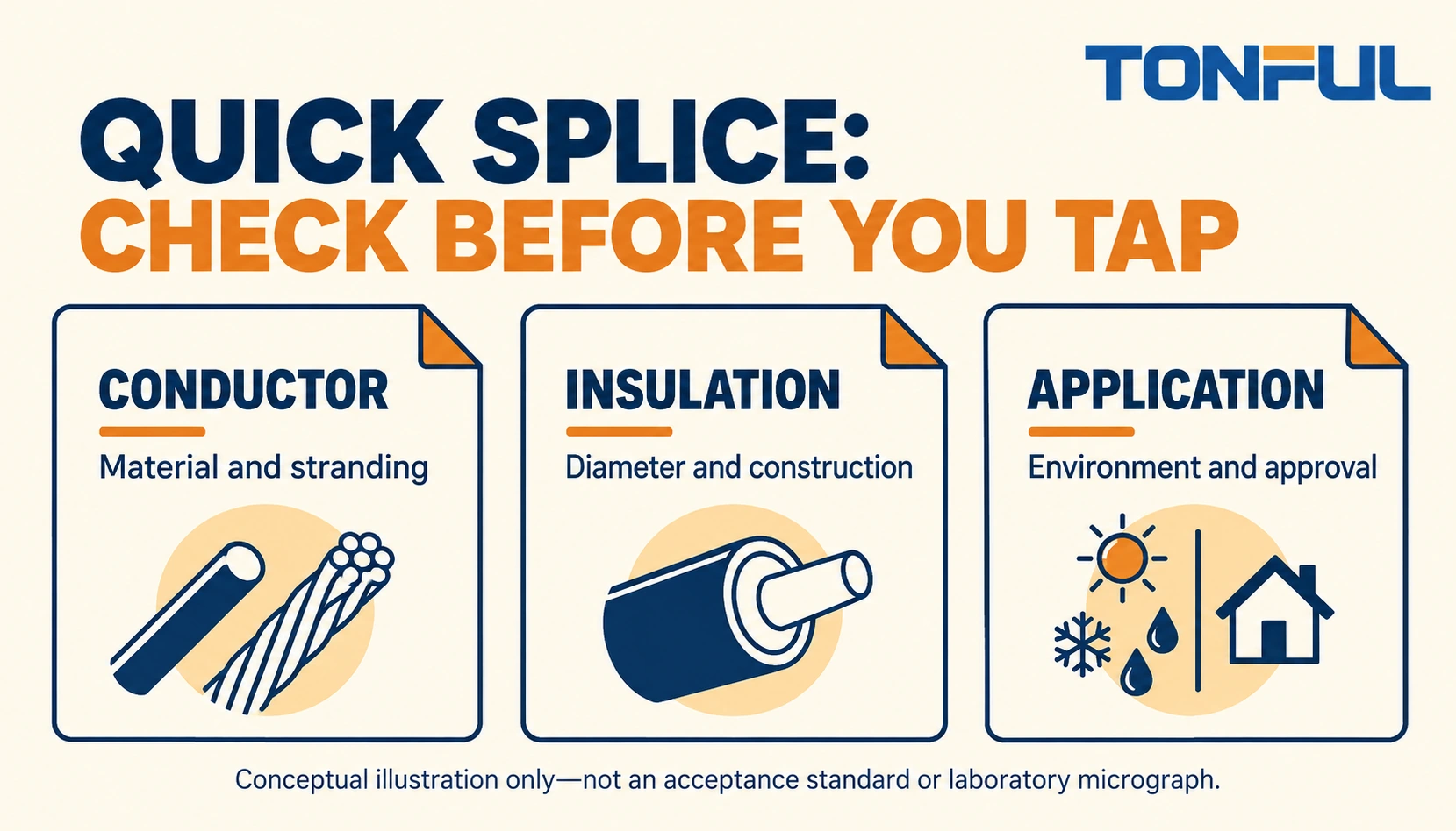
Quick splice connectors can create a branch connection without the stripping and barrel-crimp sequence used by many other splices. That convenience does not establish compatibility. The contact must work with the actual conductor and insulation, and the finished branch must be permitted in the equipment and environment. A closed plastic cover alone proves none of those conditions.
For buyers, the useful question is not whether a connector can be squeezed onto a wire. It is whether a documented wire combination, contact design and installation method can meet the application’s electrical, mechanical and environmental requirements. Use the following checks before releasing a new part or authorizing a field modification.
Jump to: Connection identity | Wire compatibility | Application limits | Installation controls | Release records | Sourcing decision
Connection identity
Separate a tap from a splice
In this guide, a quick splice is an insulation-displacement tap or splice with a contact driven into designated wire channels. A common tap design retains a continuous run wire and accepts the end of a branch wire. Other designs differ. Read the drawing before assuming that either channel accepts a through wire, multiple wires or the same gauge range.
Do not confuse this part with a quick-disconnect terminal. A disconnect has an intentional mating interface, such as a tab and receptacle. An IDC tap forms its wire connection through insulation displacement. It is not necessarily intended to be opened, reused or disconnected during servicing. A butt splice, meanwhile, normally joins prepared conductor ends inside a barrel.
Start with the actual part number
The 3M Scotchlok 560/560B product page illustrates why IDC selection belongs at part-number level: the documentation identifies the connector construction and its stated wire/application scope. Those statements are not ratings for every quick splice, and they do not establish the performance of a TONFUL alternative.
Obtain the selected supplier’s current drawing, installation instruction and permitted wire table. If the supplier offers only a photograph and a color name, stop the substitution review. Similar external shape is insufficient evidence that slot geometry, housing dimensions and conductor compatibility are interchangeable.
Wire compatibility
Check both wires independently
Record run and tap wires separately. A branch wire that fits the housing can still be outside the contact’s approved construction. Compare conductor material, nominal cross-section, strand construction, insulation material and finished outside diameter against the exact connector documentation. AWG or square millimeters describes conductor size, not the total insulated-wire diameter.
Copper, aluminum, copper-clad constructions and plated conductors are not interchangeable by assumption. Likewise, solid wire, conventional stranded wire and fine-stranded flexible wire may require different contact behavior. Never infer acceptance of a highly flexible conductor from approval of another wire with the same nominal copper area.
| Compatibility item | Record for run wire | Record for tap wire | Release question |
|---|---|---|---|
| Wire identity | Manufacturer and part number | Manufacturer and part number | Are both traceable? |
| Conductor | Material, area and stranding | Material, area and stranding | Are both listed or approved? |
| Insulation | Polymer and outside diameter | Polymer and outside diameter | Does each channel accept it? |
| Combination | Continuous wire arrangement | Branch end arrangement | Is this exact pairing allowed? |
| Processing | Routing and support | Insertion depth and support | Can the instruction be followed? |
Insulation is part of the connection system
A contact designed to displace one insulation construction may behave differently with a thicker, tougher or unusually soft jacket. The insulation must enter the intended channel without forcing the wire sideways, yet the contact must reach the conductor in the intended way. Do not strip insulation to compensate unless the approved instruction explicitly requires it.
Consider production variation rather than one convenient sample. Compare wire outside-diameter tolerances and the specified connector range. A successful assembly with a nominal sample does not cover wire near the boundary. Request engineering review when the tolerance stack approaches the documented limit or when a wire supplier changes the jacket formulation.

Application limits
A plastic enclosure is not a sealing qualification
Ask whether the installed connection encounters condensation, splash, immersion, salt, cleaning chemicals or moving-harness vibration. A cover can insulate an exposed contact without providing an environmental seal. Do not add tape or an improvised enclosure and then describe the result as waterproof. Use a connection system with evidence appropriate to the actual exposure.
For wet applications, compare the architecture with TONFUL’s waterproof wire nuts versus heat-shrink butt connector guidance. That comparison helps define alternatives; it does not authorize a specific part in a particular installation. Sealing, conductor combinations, enclosure access and repair procedure remain separate approval questions.
Respect circuit and equipment restrictions
De-energize, isolate all energy sources and verify the safe state before handling conductors. Follow the equipment manufacturer’s procedures and applicable installation rules. This article is not permission to modify building wiring, safety interlocks or a protected equipment harness simply because the voltage appears low.
Do not apply generic tap instructions to airbags or other SRS circuits, traction batteries, high-voltage vehicle circuits, medical safety functions or similarly critical systems. Use only the manufacturer’s approved connection and repair method, performed by qualified personnel. A convenience tap can also be inappropriate for shielded, twisted-pair or impedance-controlled circuits because the branch changes more than conductor continuity.
| Application question | Evidence needed | Action when absent |
|---|---|---|
| Is a branch allowed? | Equipment wiring and repair instructions | Do not modify the circuit |
| Is exposure controlled? | Environmental scope and installed-location review | Select another architecture |
| Can the wires be supported? | Routing drawing and strain-management plan | Revise mounting or routing |
| Is electrical duty covered? | Connector data and system load assessment | Obtain application approval |
| Can it be serviced safely? | Access, isolation and replacement procedure | Redesign the service point |
Installation controls
Build a first-piece instruction
Verify part identity and wire identity before setting up the station. Define the approved installation tool or closing method, wire channel orientation and branch insertion position. General-purpose pliers are not a substitute for a specified tool unless the selected connector instruction permits them. Avoid twisting the housing or using the plastic latch as a force indicator.
Seat wires as instructed and keep them from moving while driving the contact. Close the cover in the specified sequence. Inspect for displaced wires, cracked housing, incomplete contact seating and an unsecured latch. Do not use extra squeezing to conceal uncertain assembly. Where the design hides the connection, production qualification must establish the process rather than relying exclusively on external appearance.
TONFUL’s crimping tool overview is useful when considering a barrel-crimp alternative. An IDC closing operation and a barrel crimp are different processes; neither tool family should be assumed suitable for the other. Record the approved tool identifier beside the connector part number.
Qualify the process without inventing limits
For qualification, agree sample quantity, conditioning, mechanical loading and electrical measurements before testing. Include the intended run/tap combination and justified boundary conditions. Record fixture geometry, wire support and the source of every acceptance criterion. If a retention or pull test is specified, define the loading direction, pull speed, grip arrangement and failure classification.
Continuity can identify an open connection but is not proof of acceptable contact resistance or environmental durability. If resistance is evaluated, define current, instrument range and accuracy, Force/Sense positions, ambient conditions and any reference-wire subtraction. Agree how invalid tests and retests will be handled; do not repeatedly assemble new samples until a favorable result appears.
Release records
Keep installation evidence with the wire combination
Use a release record that follows the actual configuration. A generic supplier certificate is not enough to connect the tested sample to the wires purchased next month. Identify the connector lot, both wire lots, tool, instruction revision and responsible engineer. Preserve photographs of the setup and any destructive samples under their sample IDs.

| Record field | Information to enter |
|---|---|
| Configuration | Connector revision; run/tap wire identities and lots |
| Requirement source | Drawing, equipment instruction and test-plan revision |
| Installation | Tool, setup, operator authorization and first-piece result |
| Inspection | Sample IDs, observations, images and defect classification |
| Verification | Method, conditions, raw readings and criterion source |
| Decision | Release, hold or reject; authorized reviewer and date |
| Change trigger | New wire, connector revision, tool or application exposure |
When a defect is found, hold affected material and preserve the original assembly. Determine whether the issue is a wrong wire, incorrect insertion, tool setup, contact damage or an unapproved application. Replace damaged wire sections using an authorized repair method; reopening the housing does not restore insulation that has already been displaced.
For recurring defects, trace the issue back to the purchasing specification and work instruction. Preventing a wrong conductor combination at receiving is more effective than asking operators to recognize subtle differences after installation. Include wire-source changes in the change-control process even when the nominal gauge stays unchanged.
Sourcing decision
Review a proposed wire substitution
Consider a purchasing change that keeps nominal conductor size unchanged but introduces a different jacket diameter and finer stranding. This is a hypothetical review scenario, not a reported field result. The old release cannot simply be copied to the new wire. Compare both wire constructions with the permitted table, identify which run/tap combinations change and hold the alternate until its disposition is documented.
If the supplier explicitly covers the new construction, record the supporting document and check the installation method for any changed conditions. If coverage is unclear, request confirmation or select another connection. A trial that closes neatly is useful development information, but it does not replace the missing compatibility evidence. Update the bill of materials, approved-wire list and receiving identification together so the production line does not receive a mixture of old and unapproved new material.
Choose another connection when it solves the real problem
When individual service disconnection is needed, evaluate a suitable mating connector. When two prepared ends must be joined, evaluate an approved splice. When panel equipment needs a prepared stranded-wire end, review cord end terminals rather than adapting a tap connector. Product identity should follow the connection function, not a familiar catalog color.
For protected crimped alternatives, compare the available nylon-insulated terminal category with the application requirements. Insulation type alone still does not establish sealing, rating or approval. Retain the exact drawing and tooling requirements for whichever architecture is selected.
Send TONFUL the run and tap wire specifications, proposed branch function, installation environment, service restrictions and required approval documents. Use the wire terminal sourcing page to begin a part-specific discussion and request drawings, installation information and samples for your qualification plan. Do not release a quick splice solely on resemblance, price or a successful one-off squeeze test.