
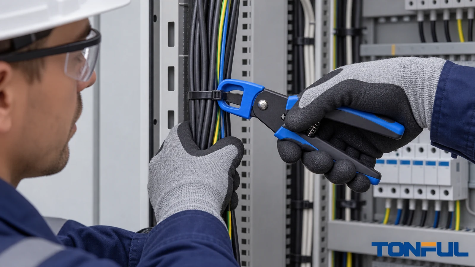
The safest way to remove a cable tie is to make room between its strap and the cable, use a tool whose blade is shielded from the insulation, and inspect the wire after the tie comes off. Do not cut blindly into a tight bundle. A nick that looks minor can expose a conductor, weaken a jacket, admit moisture or create a future failure when the harness vibrates.
The method changes with the tie. A releasable plastic tie may have a designed opening feature. A conventional ratchet tie normally needs cutting. A metal tie may need a dedicated tool and edge protection. In every case, identify what the tie is doing before removing it: some ties only organize supported wires, while others restrain movement or are part of an approved support assembly. Removing the wrong one without temporary support can let a cable shift into a moving part or pull on a terminal.
Start With Electrical and Mechanical Safety
If work is inside an electrical enclosure, machine or vehicle, follow the applicable service procedure and use competent personnel. Identify all energy sources, isolate and verify the condition required for that task, including stored energy and circuits that can re-energize. OSHA’s energy-control guidance emphasizes verifying isolation before maintenance; a switch position or extinguished indicator alone is not proof. This article is not a substitute for a site-specific lockout/tagout or vehicle-service procedure.
Also control the cable itself. Hold or support a vertical or overhead bundle before releasing its restraint. Mark the original route and photograph connector orientation, service loops and clearances. If the tie carries load, first install an approved temporary support under the responsible person’s direction; do not rely on a hand holding the bundle while cutting. Check whether adjacent ties can take the shifted load. A tight series of ties can hide a single critical support point.
| Before removal, check | Why it matters | Stop or escalate when |
|---|---|---|
| Circuit and equipment state | Prevents contact with energized or moving parts | Isolation or service procedure is unclear. |
| Tie function | Distinguishes bundling from restraint or support | Cable may fall, sag or load a connector. |
| Cable construction | Protects insulation, braid, shield, fiber or small wires | Jacket is already damaged or construction is unknown. |
| Access to strap/head | Determines safe tool approach | No blade clearance is available. |
| Replacement plan | Prevents a loose or misrouted bundle | Approved routing and replacement tie are unavailable. |
Choose a Tool That Controls Blade Contact
A purpose-designed removal tool can put a guard or nose piece between the blade and the wires. HellermannTyton’s EVOcut product information describes interchangeable nose pieces for specified plastic-tie widths and thicknesses and a design intended to cut the strap or head while protecting the harness. That is evidence for this tool and its stated tie range, not a promise that any guarded cutter works on any material or orientation.
For a conventional plastic tie, suitable options may include a compatible guarded removal tool or a small flush cutter used only when its jaws can contact the strap without touching the cable. The latter is less forgiving: do not force tips under a tight strap, twist the cutter against the jacket or place its sharp jaw beneath the tie. A utility knife is especially risky on a crowded harness because the cut direction can continue into insulation once the strap gives way. If there is no safe clearance, stop and choose a better access or tooling method rather than making a blind cut.
Do not assume a releasable tie can be opened by any improvised pick. Confirm the manufacturer-designed release feature and whether the tie is allowed to be reused after opening. The TONFUL guide to releasable and reusable cable ties distinguishes those products from a standard single-use ratchet. If the pawl is not intended for release, prying it can damage the head and still leave a sharp strap edge.
Metal ties need their own method. Their locking head and band may require a dedicated removal tool; cut metal edges can be sharp enough to injure people or abrade cable jackets. Verify the installed tie design and manufacturer procedure rather than treating it like nylon. The TONFUL stainless-steel cable-tie guide covers material and edge considerations; it is not a tool instruction for every metal band.
Step-by-Step Removal of a Conventional Plastic Tie
- Record the original state. Photograph the route, tie-head position, cable separation and nearby connectors. Note any existing jacket marks before touching the tie. If the tie is part of a traceable assembly, record the work order and location.
- Support the bundle. Prevent falling, twisting or pull on terminals. For equipment with moving parts, keep the cable out of the motion envelope. Do not transfer weight to a connector, gland or adjacent tie unless the design permits it.
- Create access without levering on insulation. Rotate the tie head gently only if the bundle and cable allow it. Choose an exposed section of strap with visible clearance. Do not shove a screwdriver between tie and cable or pull one small conductor out of a dense group.
- Select a compatible cutter. Match a guarded tool’s nose to the tie geometry. If using a flush cutter, verify that the cutting jaw remains outside the cable envelope throughout the stroke. Where the strap is completely embedded in the bundle, stop and revise the approach.
- Cut the strap or head under control. Apply only enough force to sever the tie. Hold the tail so it cannot spring into a neighboring circuit. Keep face and fingers away from the cut line; safety glasses are prudent in crowded enclosures.
- Remove all fragments. Lift the strap out rather than dragging a sharp cut end across insulation. Check behind the harness and inside the enclosure for dropped pieces that could interfere with mechanisms or airflow.
- Inspect the wires and route. Look under the former tie location and on the side facing the tool. Use adequate light and magnification if needed. Record any damage before installing a replacement.
The exact tool sequence depends on geometry. A tie around a single large jacket is different from one buried between small-gauge wires. A blade guard reduces a particular cutting hazard, but it does not protect against pulling the bundle, scratching with the tool body or replacing the tie too tightly. Keep the work controlled from the first photo through the final inspection.

Special Cases That Need a Different Approach
Releasable Plastic Ties
Use only the release motion designed for that exact head. Hold the bundle while opening; some ties release suddenly. Inspect the pawl and strap teeth afterward. If the product has a limited reuse claim or the teeth show wear, replace it. A releasable tie may be convenient for service access but should still be selected for the environment, bundle pressure and any required retention.
Stainless-Steel Ties
Identify band and lock type. Use the manufacturer-approved cutting or release method, keep a barrier between sharp metal and the jacket where specified, and collect every cut end. Do not pull a cut metal band around the bundle. Check for rust, galvanic corrosion or insulation scoring. If the tie had been installed to resist high heat or corrosion, a plastic replacement may not be acceptable.
Fiber, Data and Sensitive Harnesses
Fiber-optic cable, coaxial cable and small signal harnesses can be damaged without a visible copper nick. Excessive tie pressure can alter geometry or performance. Avoid squeezing the bundle to create tool clearance, and do not bend cable below its specified radius. If a sensitive cable shows a pinch mark, evaluate it using the cable/system owner’s acceptance criteria; visual intactness alone may be insufficient.
Dense or Inaccessible Bundles
Removing neighboring panels or opening a harness may be safer than driving a blade into a blind gap. Plan the disassembly so connectors, labels and cable order can be restored. If a tie is hidden behind another cable, do not cut through the outer cable’s route. Escalate the job when the tool approach cannot be verified by sight or controlled access.
How to Inspect for Wire Damage
Inspect in good light before the replacement tie conceals the area. Compare the former tie location with an unaffected section of the same cable. Look for jacket cuts, abrasions, indentation, whitening, flattened insulation, exposed braid or conductor, displaced shielding, and new kinks. A cut near a bend or connector deserves particular attention because movement can concentrate stress there. Do not equate “no exposed copper” with “undamaged.”
| Finding | Practical response | Release decision |
|---|---|---|
| No visible mark; geometry unchanged | Document and reroute as approved | Follow normal inspection release. |
| Superficial scuff or indentation | Measure/assess against cable maker or customer criterion | Do not improvise an acceptance limit. |
| Cut through outer jacket, exposed shield or insulation | Isolate affected circuit; refer to approved repair or replacement process | Do not release by appearance alone. |
| Exposed conductor, loose strands or arcing evidence | Keep out of service and escalate to qualified repair personnel | No energization until approved repair/test. |
| Fiber or signal cable performance concern | Perform specified optical/electrical checks | Release only to system acceptance criteria. |
If damage is uncertain, preserve a photograph and identify cable type, location and service conditions. A piece of generic electrical tape over an unknown cut is not an engineering disposition. Cable replacement, splice or localized repair may be possible, but only when permitted by the equipment maker, customer standard and applicable rules. After approved repair, the required insulation, continuity, shielding or functional checks must be documented by competent personnel.
Reinstall Without Repeating the Problem
Before adding a new tie, ask why the old one was removed. If it failed, investigate tension, sharp edges, chemical exposure, heat, UV or movement. If removal was for service, preserve access and labels. Select the approved material, length, width, mount and color. Use the TONFUL cable ties range for product-family discussion, then confirm the exact SKU and evidence. Do not substitute a different tie only because it physically closes around the bundle.
Position the new head where it can be reached without cutting toward a wire next time. Avoid placing it against an adjacent cable, sharp bracket or connector bend. Apply the approved tension; too much can pinch insulation, while too little may permit vibration abrasion. Cut the tail flush with the specified tool and verify the cut edge does not present a snag. The TONFUL cable-tie application guide gives broader routing context; the installation drawing controls the actual location and acceptance.
Check the whole route after replacement: cable support, bend radius, separation, connector strain, lid clearance and moving-part clearance. Where a tie is part of a support or restraint system, verify the mount and substrate as well; the TONFUL edge-clip tie guide illustrates why a fixing interface needs separate attention. Record the replacement part/lot and sign-off when required. A clean-looking tie head is not proof that the harness remains electrically and mechanically acceptable.

A Short Work-Record Template
| Field | Entry to capture |
|---|---|
| Work order and location | Equipment ID, harness segment, position |
| Energy-control status | Procedure reference, responsible person, verification |
| Original tie role | Bundling, restraint or support |
| Removed tie | Material/type, size and condition |
| Tool and method | Guard/nose size or approved cutter method |
| Cable inspection | Jacket, insulation, shield, bend and connector condition |
| Damage disposition | None, repair, replacement or escalation with source |
| Replacement | SKU/lot, tension method, route and final photo |
| Approval | Inspector, date and required functional tests |
This record is intentionally about process evidence rather than a generic “pass” tick box. It helps distinguish damage present before removal from damage created during cutting, and confirms that a replacement did not change routing or loading. For repetitive maintenance, review near misses and update tool selection or access design. If the same tie is routinely hard to reach, the assembly may need a serviceability improvement.
Work With TONFUL
TONFUL can help compare cable-tie styles for a maintainable harness route, including conventional, releasable and metal families. Send the cable diameter, route, environment, tie function, access constraints and required replacement documentation. Ask for exact-product drawings and approved installation conditions. A product recommendation does not replace electrical isolation, cable-damage assessment or the equipment owner’s repair rules. The safer outcome is a tie that fits the application and can be removed without forcing a blade against the wires.
Technical Sources
- HellermannTyton EVOcut plastic-tie removal tool: manufacturer’s guarded-tool purpose and compatible-nose concept; check the exact tool version and tie range.
- OSHA, energy-control verification guidance: isolation and verification principles for maintenance; apply the site’s governing rules and equipment procedure.