
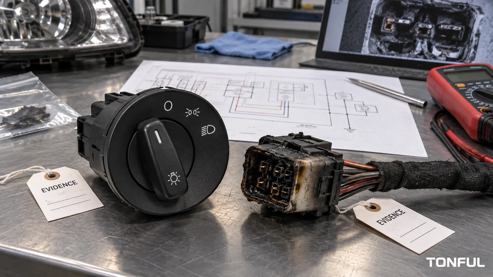
A melted headlight switch or connector is evidence of heat, not a complete root-cause diagnosis. Heat may develop from resistance at a contact or terminal, excessive circuit current, an incorrect lamp load, damaged crimps, poor repairs, connector movement, contamination, or a control architecture operating outside its intended design. Replacing only the visibly burned part can recreate the failure.
TONFUL’s current headlight-switch range presents vehicle applications and OE references. Confirm the exact vehicle, complete OE reference, connector, pinout, functions, approved sample and project-specific validation plan before ordering or testing.
Quick Evidence Matrix

Conceptual illustration only – not a vehicle procedure, laboratory result, universal limit, or acceptance standard.
Use the illustration to organize the first inspection, but do not select a cause from appearance alone. Measure current and loaded voltage drop, inspect both mating halves, preserve the original condition and confirm whether the initiating mechanism is resistance, excess current, mechanical damage or contamination.
For every cause below, identify the affected component, circuit path and vehicle or sample, then preserve objective evidence before disconnecting parts. Numeric requirements must cite the product drawing, OEM or customer specification, approved repair procedure or investigation plan. This common rule is stated once here; each cause section defines its own evidence and corrective-action path.
The Heating Mechanism: Current, Resistance and Feedback
Electrical heating in a resistive path can be expressed as P = I²R, where P is power converted to heat, I is current through the path and R is resistance of that path. The equation helps separate two failure routes that can produce similar melted plastic.
Local resistance increase: A loose terminal, reduced spring force, oxidation, contamination, worn switch contact, damaged crimp or broken conductor strands can increase resistance at a small area. Normal circuit current passing through that localized resistance generates concentrated heat. For illustration only, if a suspect interface carries 8 A and has 0.05 Ω resistance, its local dissipation is 8² × 0.05 = 3.2 W. This is not an acceptance limit; it simply shows how several watts can be released inside a small connector cavity.
Excess current: An incorrect lamp, added lighting, modified wiring or downstream fault can raise current through contacts, terminals and conductors. Because current is squared in the equation, doubling current would produce four times the resistive heating if resistance stayed constant. Actual circuit behavior must be measured because resistance, supply voltage, protection and temperature may also change.
A thermal feedback loop can accelerate damage: heat → reduced terminal spring force or material degradation → higher resistance → more heat. Softened housing may move a terminal; weakened spring force reduces real contact area; oxidation or arcing further increases resistance. The most burned surface may therefore be secondary damage rather than the original defect.
Six Root-Cause Paths
High Resistance at Switch Contacts
Observable evidence can include local heat, discoloration, unstable lighting and voltage loss across a closed contact. Contain the vehicle or lot, preserve the switch position and load condition, then compare loaded drop, contact condition and thermal evidence. Confirm with controlled measurements or teardown; correct the contact design, contamination or wear mechanism and update monitoring.
Record loaded voltage drop across the closed switch path, current, switch position, temperature location and the first cycle or operating condition that produced instability. Teardown should look for contact wear, oxide, pitting, transfer, contamination and spring or carrier damage. A permanent action must address the confirmed contact mechanism, not simply replace the housing around it.
Low Terminal Grip or Mating Damage
A spread, backed-out, corroded or fretted terminal reduces effective contact area and can heat both connector and switch. Photograph before disconnecting, check retention and mating surfaces, and inspect both halves. Replace all heat-damaged mating parts required by the repair, correct terminal selection or insertion, and add retention and connector inspection controls.
Measure terminal retention or contact force only with the approved method and tooling; an oversized probe can further spread the terminal. Compare mating marks and heat location across both halves. Permanent action can require replacement of both mating components, corrected terminal selection or insertion, improved secondary locking, harness support and receiving or assembly checks.
Crimp, Wire or Repair Defects
Cut strands, loose crimps, conductor corrosion, undersized repair wire and poorly executed splices can concentrate resistance. Quarantine previous repairs, record wire and terminal identity, measure the suspect path under load and use cross-section or pull evidence when required. Correct the repair process and update tooling, inspection and technician authorization.
Evidence should identify wire gauge, conductor construction, terminal, seal, crimp tool and cavity, repair materials and operator or process traceability. Pull testing, crimp-height measurement or cross-section analysis may be required by the investigation plan. The corrective action should control tooling, strip length, conductor condition, terminal compatibility and repair authorization.
Excess Current or Incorrect Lamp Load
Higher-than-approved current can overheat a sound interface. Record lamp or driver type, modifications, fuse rating, current waveform, downstream shorts and accessory wiring. Confirm against the vehicle specification rather than appearance. Restore the approved load and protection, repair shorts, and prevent uncontrolled substitutions.
Measure operating current and, when relevant, inrush or waveform under the condition that caused heating. Compare the installed lamp or electronic driver, fuse, wire and modifications with vehicle-specific documentation. A permanent repair removes unauthorized loads or shorts and restores the approved circuit configuration; installing a higher-rated fuse is not a corrective action unless the controlled vehicle documentation explicitly requires it.
Harness Strain, Vibration and Poor Support
Connector movement, tight routing or unsupported mass can reduce contact stability and damage crimps or latches. Evidence includes position-sensitive flicker, fretting and strain marks. Reproduce only under controlled conditions, then correct routing, retention and support and add installation checks to the control plan.
Photograph routing, bend radius, connector seating, latch condition, support points and evidence of rubbing before moving the harness. Controlled movement can help confirm an intermittent connection, but stop if it increases heat or arcing. Permanent action must correct routing, strain relief, clipping, connector engagement or mounting interference and add an installation verification step.
Moisture, Contamination and Housing Damage
Water, salts, chemicals, dust and damaged seals can corrode contacts and alter insulation or terminal force. Preserve residue for investigation, inspect seals and ingress paths, and distinguish initiating contamination from heat-created damage. Correct sealing, materials, handling or enclosure design according to the applicable environment specification.
Document residue location, color, odor, corrosion products, seal condition and a plausible ingress route before cleaning. Determine whether contamination initiated resistance or entered after thermal deformation. Corrective action may involve sealing, enclosure, drainage, material compatibility, handling or cleaning controls tied to the approved environmental requirements.
Why Can the Connector Melt Without Blowing the Fuse?
A fuse is selected primarily to protect wiring against specified overcurrent conditions. It does not measure connector temperature or directly detect every high-resistance interface. A loose or oxidized terminal can create enough local I²R heating to soften or melt nearby plastic while total circuit current remains below the fuse’s opening threshold.
For example, adding resistance at one connector may actually reduce total circuit current while concentrating power at that damaged interface. Whether a fuse opens depends on its current-time behavior, the installed fuse, circuit current and duration, not merely on the presence of heat. Never replace a fuse with a higher rating to stop nuisance operation. Verify the specified fuse and circuit configuration, then measure current and loaded voltage drop and repair the initiating high-resistance or overcurrent cause.
Distinguish the Initiating Fault From Secondary Heat Damage
Thermal damage spreads. A hot terminal can soften a housing, reduce neighboring terminal retention, char insulation and oxidize surfaces that were initially sound. Conversely, an overloaded circuit may heat several conductors and interfaces without one original loose terminal. Root-cause analysis should therefore map the heat pattern, compare cavities, preserve the first-discovered condition and correlate physical evidence with current and voltage-drop measurements.
Do not assume the darkest or most deformed part started the event. Evidence suggesting an initiating fault can include a localized voltage-drop peak, asymmetric mating marks, fretting, a defective crimp, contamination at an ingress path or a documented unauthorized load. Secondary damage can include broad charring, transferred residue, housing distortion and terminals displaced only after plastic softened. Record which conclusion is observed, inferred or confirmed by teardown or laboratory analysis.
Test or Investigation Record

This conceptual record layout supports traceability; it does not replace the controlled test or investigation form.
Use this vertical investigation matrix to connect each failure area with evidence and a confirmation method:
| Failure area | Evidence to collect | Root-cause confirmation |
|---|---|---|
| Switch contact | Loaded voltage drop, operating current, discoloration, temperature location and teardown photographs | Contact wear, pitting, spring degradation or contamination confirmed within the defined switch path |
| Terminal interface | Retention evidence, mating marks, cavity position, thermal pattern and both connector halves | Reduced contact force, incomplete engagement, fretting or corrosion confirmed |
| Crimp or wire | Wire and terminal identity, crimp height where applicable, pull result, cross-section and conductor condition | Crimp, broken-strand, corrosion or undersized-conductor defect confirmed |
| Excess current | Current waveform, installed lamp or driver, modifications, downstream fault evidence and fuse identity | Measured load exceeds the approved vehicle configuration or a short is located |
| Harness strain | Routing photographs, bend and support condition, latch status and controlled movement response | Strain, vibration, interference or incomplete connector seating reproduces the instability |
| Environment | Residue, seal condition, housing damage, corrosion pattern and ingress path | Contamination source and path are confirmed and distinguished from post-heat exposure |
| Secondary damage | Heat map, neighboring cavities, material deformation and event sequence | Damage propagation is separated from the initiating electrical or mechanical cause |
The case record should also identify the vehicle or sample, part and lot, switch state, operating condition, instruments, acceptance-source documents, immediate containment, affected population, permanent action, control-plan change, owner and closure date. Preserve raw measurements and original photographs; reconnecting a damaged interface can change the evidence.
Internal Links and Decision Path
- TONFUL Headlight Switch Manufacturer
- Headlight Switch, Relay or BCM Control Guide
- Headlight Switch Multimeter Test
- Bad Headlight Switch Symptoms
- Headlight Switch Buying Guide
Supplier, Release, and Change Control
For an RFQ or validation request, provide the vehicle, OE chain, connector, function matrix, architecture, load definition, environment, sample quantity and acceptance sources. Request controlled drawings, nonconformance handling and change notification.
Receiving inspection should compare lot identity, housing, connector, terminals and functions with the approved sample. Define reaction plans for discrepancies and changes requiring notice or reapproval.
Final Release Checklist
- Scope, application, part revision, sample quantity and lot are identified.
- Electrical architecture, functions, loads, environment and conditions are documented.
- Equipment, fixtures, probes, ranges, accuracy and calibration status are recorded.
- Actual results, failure modes, photographs and raw-data references are retained.
- Every limit points to an approved source; no universal value is invented.
- Invalid tests, retests, deviations and unresolved items have documented disposition.
- Approved sample, receiving controls, traceability and change notification are defined.
- Release identifies reviewer, date, approved scope and closure evidence.
Planning Review Before Execution
Before testing, confirm circuit scope, safety controls, instruments, evidence needs and acceptance sources. Resolve conflicting documents before selecting limits.
Evidence Review After Testing
An independent reviewer should be able to reconstruct the decision from sample identity, setup photographs, calibration status, raw readings, event logs, environmental records and acceptance sources. Separate observed symptoms from confirmed causes. Open items need an owner, due date, affected-stock decision and closure evidence; conditional approval must state its exact scope.
Follow a Controlled Diagnostic Order
Begin with containment: stop repeated operation where heat, odor, smoke or softened insulation is present, follow the vehicle isolation procedure and quarantine affected parts or stock. Record traceability, modifications, previous repairs, fuse and lamp information, switch position and the conditions that produced the event. Photograph the switch and connector before separation.
Continue with visual inspection, terminal retention, connector engagement and wire or crimp review. Measure both current and loaded voltage drop under an authorized setup because resistance heating and excessive current require different corrective actions. Compare the switch path, each mating interface, relay or module output, grounds and lamp-side circuit. Use thermal evidence as a location clue, not a substitute for electrical measurement.
Escalate to teardown, cross-section, material analysis or environmental investigation when simpler evidence cannot confirm the cause. The final report should separate initiating cause from secondary heat damage, identify affected population and verify the permanent action. Update drawings, work instructions, inspection, training, supplier controls and field-repair instructions as applicable. A new switch installed into a heat-distorted connector is not a complete repair.
Work With TONFUL
Send TONFUL the complete application and evidence package rather than only a switch photograph or symptom. TONFUL can compare the request with current headlight-switch applications and OE references, then align sample review and project-specific validation requirements. Final approval remains tied to controlled documentation, agreed tests and the approved sample.