
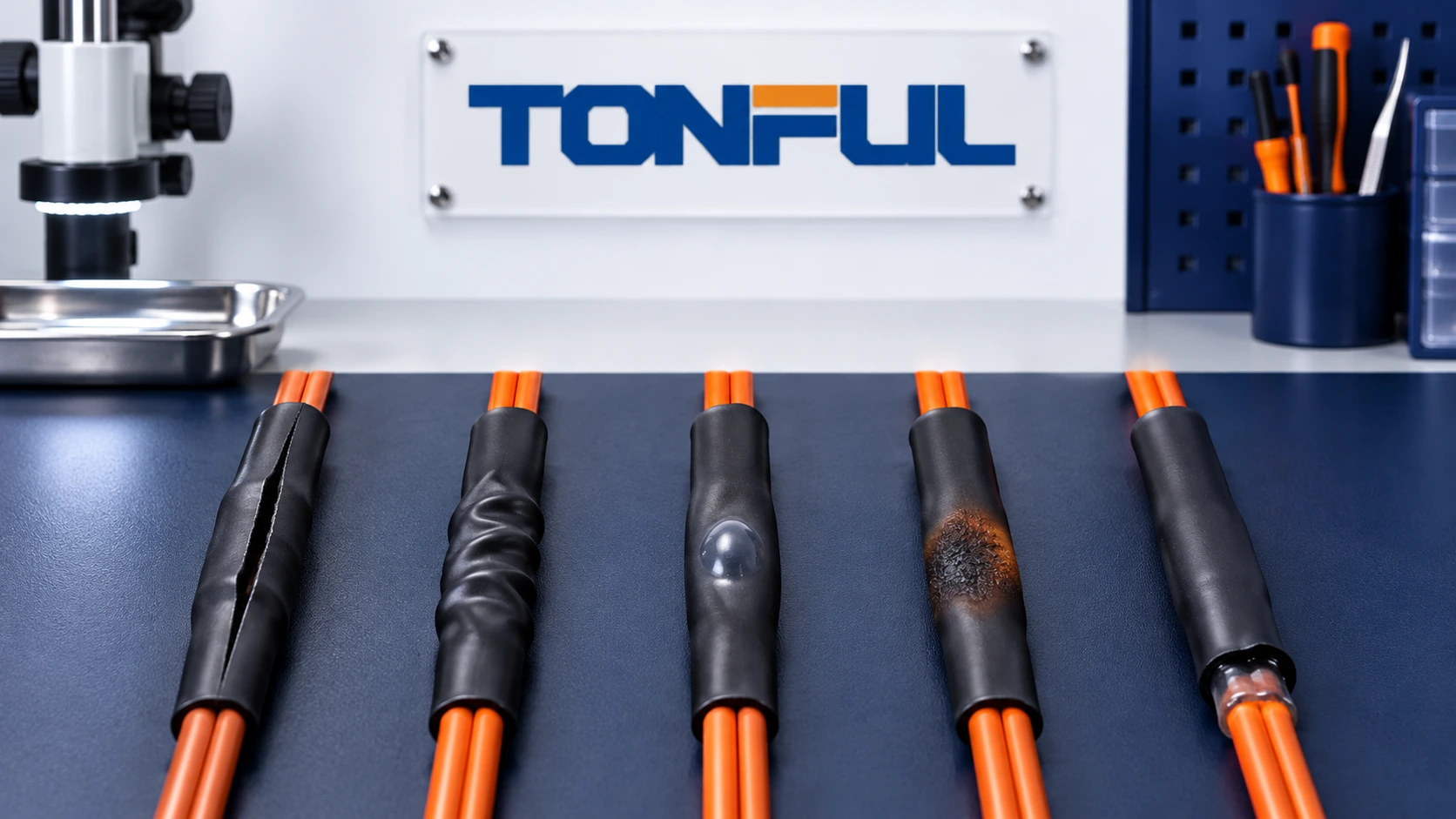
Heat shrink tubing defects are evidence, not diagnoses. A split may result from a sharp edge, forced installation, wrong size, material damage or excessive heat. Wrinkles can indicate uneven heating, oversizing or trapped geometry, but some temporary chill marks may disappear as recovery finishes. A visible adhesive bead can occur even when an internal leak path remains.
The right response is to quarantine affected work, preserve samples and trace the symptom back through product identity, dimensions, substrate, preparation and heating records. This guide provides a repeatable method for investigating splits, wrinkles, bubbles, incomplete recovery and seal failures without inventing universal temperature or appearance limits.
On this page: Containment | Diagnostic order | Defects | Heating | Sealing | Prevention
Contain the Problem Before Reworking
Stop the process and identify the affected machine, operator, time window, work order, tubing product and lot, cut length, substrate and heating equipment. Segregate finished assemblies made since the last verified good check. Do not immediately reheat, trim or cover every defect; those actions can destroy the evidence needed to find the cause.
Photograph the defect before handling it. Record viewing direction, scale and exact location relative to tube ends, crimp, connector, sharp edge or heat source. Keep representative good and failed samples. If the defect could expose a conductor, compromise insulation or allow moisture entry, follow the project’s nonconforming-material and electrical-safety procedure.
Use a Repeatable Diagnostic Order
Investigate in a sequence that separates incoming material, application design and process variation:
- Confirm the exact product, size, lot, storage history and shelf-life status where applicable.
- Measure supplied dimensions without stretching or distorting the soft tube.
- Compare maximum pass-over geometry and minimum substrate geometry with the approved size window.
- Inspect substrate edges, contamination, moisture, crimp condition and placement.
- Review cut length, overlap and expected longitudinal change.
- Verify heat source, nozzle/reflector, programmed recipe or setting, distance, motion, fixture and cycle time.
- Compare a retained good sample using the same controlled method.
- Section development samples when internal liner distribution, voids or damage cannot be seen externally.
- Repeat required electrical, sealing and mechanical tests before disposition.
The heat shrink tubing size guide explains supplied ID, recovered ID, wall and longitudinal change. TE Connectivity’s official tubing sizing guidance also notes that forcing tubing over a substrate or recovering it over sharp edges can lead to tearing or splitting, and that excessive or insufficient installation heat creates different defects. Its recommendations apply to the referenced TE products and should not be copied as universal acceptance limits.

A fixed diagnostic order prevents rework from destroying evidence and distinguishes material, design and installation causes.
Failure-to-Evidence Matrix
| Observable symptom | Evidence to collect | Likely directions to confirm | Immediate containment | Permanent corrective action |
|---|---|---|---|---|
| Longitudinal split | Split origin, edge condition, size, heating record and material lot | Forced pass-over, sharp edge, overstretch, overheating or damaged tube | Stop release; inspect exposed insulation | Correct edge/size/process; validate new sample |
| Circumferential tear | Cut quality, nick location, tool marks and tensile condition | Damaged cut edge, handling nick or embrittled material | Segregate same cut batch | Repair cutting method and storage control |
| Persistent wrinkles | Tube-to-substrate ratio, heating pattern, fixture and wall distribution | Oversizing, uneven heat, trapped material or complex geometry | Hold appearance/function decision | Adjust size, fixture or qualified heating method |
| Bubbles or blisters | Surface preparation, moisture, heat intensity and cross-section | Trapped air/moisture, contamination, local overheating or incompatible substrate | Stop reheating failed samples | Dry/clean substrate; correct heat profile/material |
| Scorching or gloss change | Surface temperature evidence, distance and dwell | Excess temperature, stationary heat source or wrong nozzle | Inspect adjacent insulation | Add process window, motion control and protection |
| Incomplete recovery | Final dimensions, cold zones, heat equipment and cycle | Insufficient energy, wrong product, heat sink or poor access | Hold fit and insulation approval | Qualify time/temperature/fixture for assembly |
| Tube moved or shortened | Initial position, cut length and longitudinal-change data | Uncontrolled axial change, air movement or handling | Check required overlap | Revise cut/position dimensions and fixture |
| No adhesive flow | Liner identity, substrate temperature, cross-section and heat input | Insufficient heating, wrong product, aged liner or heat sink | Do not accept as sealed | Confirm identity and qualify thermal process |
| Adhesive bead but leak remains | Leak path, wire valleys, overlap, surface and sectioning | Poor wetting, multi-wire channel, void or upstream wicking | Quarantine sealing claim | Redesign geometry/liner volume and validate |
This matrix guides investigation; it is not a universal acceptance standard. Product drawings and customer specifications decide whether a wrinkle, color change or adhesive bead is acceptable. A cosmetic defect and a functional failure can look similar, so preserve objective test evidence.
Why Heat Shrink Tubing Splits
A split usually starts where mechanical or thermal stress is concentrated. Sharp metal edges, terminal wings, burrs and cut marks can puncture the hot softened tube. Stretching an undersized supplied tube over a connector preloads the material before heating. At recovery, that local strain can exceed the remaining strength.
Excessive heat may embrittle, thin or burn the wall, while an aggressive heat stream can create a hot spot beside a cold region. Conversely, a tube that has not fully recovered can remain loose and then split later under abrasion or movement. Storage damage, UV exposure, contamination or an unapproved material substitution may also contribute.

Conceptual illustration only—not an acceptance standard. Locate the origin before deciding whether size, geometry, material or heating caused the split.
Why Wrinkles Form
Heat-gun recovery rarely heats the full circumference at exactly the same rate. A hot region starts shrinking while a cooler region retains its expanded dimensions, producing temporary waves or chill marks. Continued controlled heating may remove them for products designed for that method. Persistent folds, however, can trap air, reduce contact, concentrate abrasion or interrupt a sealing path.
Oversized tubing has more material to redistribute and can wrinkle on a small substrate. Long sections may recover unevenly or accumulate axial material when longitudinal change and fixture constraints conflict. Irregular components, abrupt diameter transitions and branches also create surplus material that cannot lie flat.
Do not prescribe “keep heating until smooth” without limits. Additional heat may scorch the outer wall, move adhesive or damage the substrate. Compare the product instruction, measured final dimensions and functional requirements. For repeat production, consider a reflector, controlled-air fixture, oven or infrared system when it improves circumferential uniformity. The heat gun, oven and infrared comparison explains the process tradeoffs.
Why Bubbles and Blisters Appear
Bubbles can form when air, moisture, solvent or contamination is trapped beneath the recovering wall. A wet cable, recently cleaned surface or porous substrate may release vapor as temperature rises. Local overheating can soften or degrade the polymer and create a blister-like appearance. In dual-wall tubing, uneven liner flow may also create internal pockets that become visible through the outer wall.
Record whether the bubble moves, collapses after cooling or corresponds to an internal void. Section only designated samples using a controlled preparation method. Inspect for substrate damage, liner wetting and foreign material. A clear tube can help development inspection, but its material and performance must still match the application.
Separate Heating Defects From Product Defects
Run a controlled comparison using identified tubing from the same lot and, when possible, a retained approved lot. Use production substrates at tolerance extremes. Apply the approved process while recording actual conditions. If only one heat station or nozzle reproduces the defect, investigate equipment and fixture variation. If all controlled stations reproduce it on one lot, escalate material identity and property review.
Do not use an uncalibrated heat-gun dial as evidence of tube temperature. The substrate mass, airflow, distance, angle, reflector and ambient conditions influence recovery. An infrared surface reading also requires defined emissivity and field of view. Use the parameters and measurement method established by the qualified process.
The heat shrink testing guide describes sample identity, equipment records and acceptance sources. Preserve raw data and failed parts rather than recording only “operator error” or “material issue.”
Plan Samples Before the Trial
Define sample quantity and allocation before changing the process. Keep an unheated piece from each evaluated lot for identity and dimensional checks. Use separate specimens when sectioning or pull testing would destroy evidence needed for sealing or electrical tests. If a sequence is intended, document whether thermal conditioning occurs before flexing, leakage or electrical retest because order can change the result.
State how invalid tests, equipment interruptions and replacement samples are handled. A sample that fails for a confirmed product or process reason is not “invalid” merely because another specimen passes. The test-plan owner should approve the sample basis, variants and disposition before execution, especially when a correction will release quarantined production.
Separate Cosmetic Appearance From Functional Acceptance
Create an approved visual standard with real production images, viewing conditions and clearly identified defect locations. Define which characteristics are informational, which require engineering review and which are rejectable. A shallow surface wave that does not affect wall, fit or sealing may have a different disposition from a folded channel crossing a seal zone. Similarly, slight adhesive flow can be acceptable for one design but evidence of incorrect placement in another.
Visual inspection should be supported by measurements and functional evidence. Record final position, required overlap, recovered dimensions and wall where specified. For electrical insulation, sealing, strain relief or environmental protection, use the applicable test rather than appearance as a substitute. The heat shrink installation defect checklist provides a practical structure for first-piece and final inspection.
Why Adhesive-Lined Tubing Fails to Seal
Adhesive flow and sealing are related but not identical. The liner must reach its process condition, wet compatible clean surfaces and occupy the intended gap. Oil, silicone residue, oxidation, water and some insulation compounds can reduce wetting. A cylindrical sleeve may leave channels between multiple wires even when adhesive appears at both ends.
An upstream connector or damaged insulation can admit water that wicks under an otherwise sound sleeve. Excessive adhesive flow can leave a thin internal region, while insufficient heat can leave a solid liner that never wets the substrate. Bending the assembly before cooling can disturb the seal.
Use the adhesive-lined tubing guide to define substrate, overlap, liner volume and conditioning. Validate the exact assembly with the required leakage, ingress, electrical and mechanical method. Do not convert a water-dunk demonstration, visible end bead or material claim into an IP rating.

Seal investigations must distinguish liner flow from verified barrier performance and examine moisture paths outside the visible sleeve ends.
Convert the Root Cause Into Process Control
Close the investigation with evidence that the correction works. Update the drawing, approved product/size, work instruction, fixture, heating recipe, inspection standard and training as applicable. Define first-piece checks after setup, tool maintenance, material change and restart. Challenge mistake-proofing features rather than assuming they function.
| Root-cause area | Prevention control | Verification record |
|---|---|---|
| Wrong size or product | Barcode/part verification and controlled bill of material | First-piece identity and dimensions |
| Substrate edge or contamination | Drawing requirement, preparation method and visual standard | Pre-shrink inspection |
| Cut damage | Qualified cutter and blade-maintenance rule | Cut-edge sample check |
| Heating variation | Defined equipment, fixture and process window | Station log and first-piece result |
| Position/overlap | Stop, fixture or marked placement | Measured overlap record |
| Seal geometry | Approved wire combination and assembly test | Leak/ingress and section evidence |
| Storage/aging | Packaging, environmental and stock-rotation controls | Lot and storage history |
Audit recurrence by defect type, lot, product, station and application. Verify corrective-action effectiveness after an appropriate production interval. A lower defect count is useful only when inspection sensitivity and product mix remain comparable.

A closed corrective action links the confirmed cause to drawing, material, equipment, instruction and training changes, then verifies effectiveness with defined production evidence.
Control Supplier and Process Changes
At production level, authorize heat-source, nozzle, reflector, fixture, recipe and line-location changes. Use the incoming inspection checklist to verify product identity and dimensions before the lot enters the process. Retain enough traceability to connect a field or factory defect to tubing lot, work order, station and approved process revision.
Work With TONFUL
Send TONFUL the failed-sample photos, product and lot, substrate drawing, dimensions, installation process, exposure, test method and required acceptance criteria. TONFUL can help review heat shrink tubing selection and production-intent samples. Final root cause and approval must be based on the controlled assembly evidence, not on appearance alone.
—