
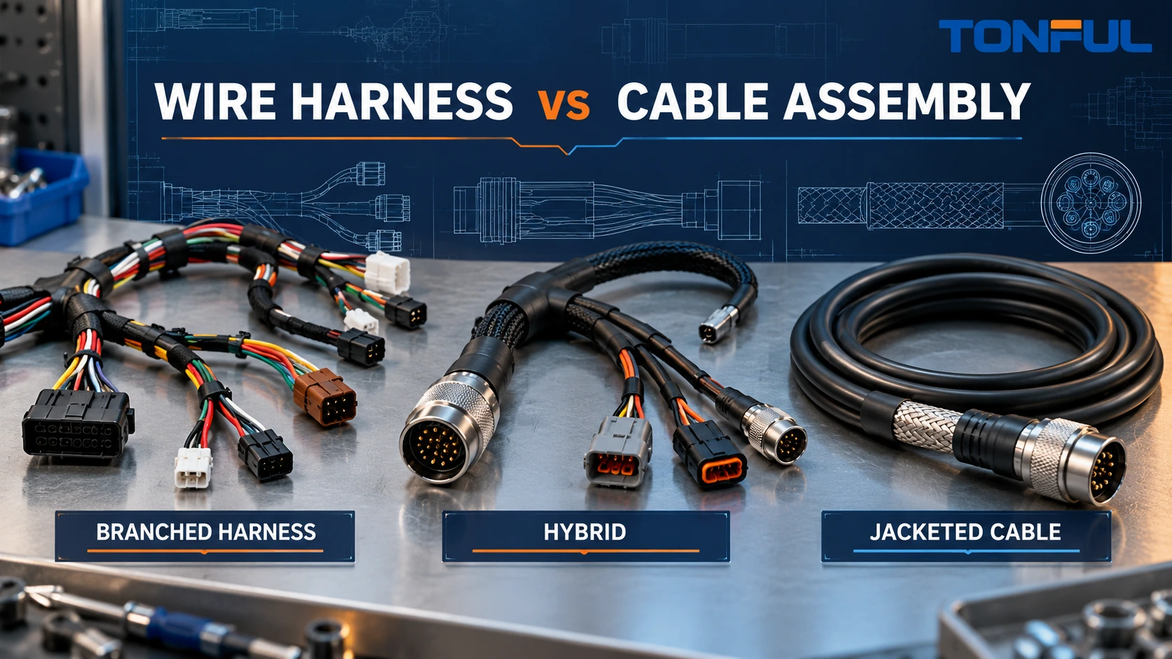
The choice between a wire harness and a cable assembly should not begin with the supplier’s preferred product name. It should begin with the electrical circuits, physical routing, environmental exposure, interfaces and verification required by the finished equipment. In common purchasing language, a wire harness often organizes multiple discrete wires into branches, while a cable assembly often uses a jacketed or purpose-built cable between defined endpoints. Real products can combine both structures.
This overlap matters. A buyer who requests “a ten-wire cable” may receive a round jacketed construction even though the equipment needs separate breakouts. Another buyer may request “a harness” while expecting controlled impedance, a continuous shield and a molded connector normally associated with a data cable assembly. The solution is not to argue over terminology; it is to specify the construction and acceptance evidence.
On this page: Practical distinction | Decision matrix | Interfaces | Environment | Testing | RFQ
A Practical Distinction, Not an Absolute Definition
The words are not governed by one universal commercial taxonomy. IPC notes that different parts of the industry use different definitions and, for the purpose of IPC/WHMA-A-620, the terms cable and wire harness are used interchangeably. IPC’s official announcement for IPC/WHMA-A-620E states that the standard covers manufacturing practices, materials, methods, tests and acceptance criteria for cable and wire harness assemblies. This supports workmanship control; it does not force every buyer to use the same catalog label.
For RFQ and design discussion, the following working distinction is useful:
- A wire harness commonly routes separate insulated wires through clips, ties, tape, braid, conduit or sleeves. It may contain many branches and connector breakouts shaped to the equipment.
- A cable assembly commonly starts with a manufactured cable construction: multiple conductors, pairs, coaxial cores or fibers held in a common jacket, often with shielding or controlled geometry. Connectors terminate one or both ends.
- A hybrid assembly may begin with a jacketed cable and transition into discrete branches, combine power and signal subassemblies, or include both overmolded cable ends and harness-style breakouts.
Neither name proves performance. A loose bundle is not automatically flexible, and a jacketed cable is not automatically waterproof, shielded or suitable for continuous motion. Product evidence must match the exact construction.

Conceptual illustration only—not an acceptance standard or laboratory image. The drawing and approved sample define the actual construction.
Wire Harness vs Cable Assembly Decision Matrix
Use architecture and installation needs to select the starting structure.
| Decision factor | Wire-harness approach often fits | Cable-assembly approach often fits | Required evidence |
|---|---|---|---|
| Circuit routing | Multiple destinations and irregular branches | Defined endpoint-to-endpoint route | Harness layout or cable assembly drawing |
| Conductor geometry | Discrete wires can separate and regroup | Pairing, coaxial geometry or shield coverage must remain controlled | Wire/cable specification and termination instructions |
| Installation space | Flat or shaped routing through equipment | Round or defined cable envelope | Routing model, bend limits and interface dimensions |
| Mechanical protection | Local sleeve, braid, tape or conduit by zone | Continuous outer jacket or overmold | Material, coverage and environmental evidence |
| Service access | Branches and individual circuits may need identification | Complete cable may be replaced as one unit | Labels, pinout and service procedure |
| Motion | Static routing or project-defined flex zones | Purpose-designed flex cable may be preferable | Bend radius, flex method and cycle plan |
| EMC/shielding | Local shielded wires or subcables can be integrated | Continuous foil/braid and controlled termination may be easier | Shield construction and bonding test |
| Manufacturing | Cut, strip, crimp, splice, route and secure discrete wires | Prepare cable, manage shield/jacket and terminate connectors | Process flow, tooling and inspection plan |
A harness is usually the clearer starting point when circuits fan out to sensors, switches, motors and a control unit. A cable assembly is often clearer for USB, Ethernet, coaxial, machine-vision or other point-to-point links whose electrical behavior depends on cable geometry. Equipment frequently needs both.
The TONFUL custom wire harness capability provides a project discussion entry point. Do not infer a specific connector, cable construction, test level or certification from a general capability page; confirm the exact drawing, BOM and validation scope.
Define Every Interface and Branch
Start With a Controlled Connectivity Record
List each circuit from source to destination. Give connectors unique IDs such as J1 and J2, and give every cavity a controlled number. Record wire or cable ID, conductor size, color or marking, terminal, seal, splice, shield connection and electrical function. A connector picture without cavity orientation is not a pinout.
For a branched harness, the drawing should locate every breakout from a defined datum. State branch length, tolerance, measurement method and whether the dimension is measured to the connector face, wire exit, clip center or another point. Define service loops only where installation or maintenance requires them. Uncontrolled extra length can cause abrasion, interference or inconsistent assembly.
For a cable assembly, identify the cable manufacturer part or controlled construction. Specify conductor count, gauge, insulation, jacket, pair assignment, shield, drain wire, impedance where applicable, minimum bend requirement and permitted jacket strip length. TONFUL’s wire AWG and insulation selection guide explains why conductor size and insulation must be selected from electrical, mechanical and environmental requirements rather than appearance.
Specify Mating and Mechanical Interfaces
Record connector manufacturer and complete part number when required, plus acceptable alternatives and approval status. Include backshells, wedges, seals, boots, keying, latch direction, panel cutouts and mating components. For ring lugs or other bolted terminals, define stud size, orientation, stack-up and torque source without inventing a universal value.
Overmolding can provide strain transition, sealing and an installation shape, but its success depends on cable-jacket adhesion, connector preparation, material compatibility and process control. The TONFUL overmolded cable assembly guide covers those design inputs in greater depth.
Specify Protection From the Real Environment
“Industrial,” “automotive grade” and “outdoor” are not test conditions. Define the installation location and exposures: operating and storage temperature, fluids, UV, moisture, dust, vibration, shock, abrasion, flexing, pull, cleaning chemicals and nearby heat sources. State whether the assembly is inside a sealed enclosure, routed through a moving hinge or directly exposed.
Protection can be zoned. A wire harness may use abrasion sleeve near a bracket, heat-resistant covering near a motor and an unwrapped branch inside an enclosure. A cable assembly may use a continuous jacket but still need a boot, gland, overmold or conduit at the interface. Coverage drawings should identify starts, stops, overlaps, breakout transitions and prohibited areas.
Do not assign an IP rating to a wire, connector or sleeve merely because the finished system needs ingress protection. The rating applies only to the evaluated product or enclosure configuration and conditions. If sealing is required, define mated connectors, cavity plugs, wire seals, backshells, grommets, overmolds and pressure boundaries, then validate the complete assembly or installed system as required.
The TONFUL wire harness protection guide can help compare braid, conduit, tape, heat-shrink tubing and other protection methods, but the project drawing must define the final material and coverage.

Conceptual illustration only—not an acceptance standard or laboratory image. Environmental zones and protection details must come from controlled project requirements.
Build Testing Around the Circuit and Risk
Continuity is a basic check, not complete validation. A test plan should identify sample quantity, production coverage, fixture revision, equipment, accuracy, test voltage/current where relevant, acceptance-source document, invalid-test rules and retained records. Requirements depend on circuit risk and construction.
| Verification | What it can establish | Important limitation |
|---|---|---|
| Visual and dimensional inspection | Correct parts, routing, lengths, labels and workmanship | Cannot prove hidden electrical defects by itself |
| Point-to-point continuity | Expected conductive paths and gross opens | May miss intermittent faults or unsuitable contact resistance |
| Short/miswire test | Unwanted connections between defined nodes | Test matrix must include every relevant circuit state |
| Contact/path resistance | Resistance of the defined path under controlled setup | Probe locations, wire length, current and compensation affect results |
| Insulation resistance | Leakage resistance between isolated circuits | Test voltage and acceptance limit must come from the approved requirement |
| Dielectric withstand/hi-pot | Ability to withstand a specified potential for a specified time | Not interchangeable with insulation-resistance testing |
| Pull/retention test | Mechanical integrity of a crimp, terminal or connector feature | Method and limit are product- and specification-specific |
| Functional test | Behavior with loads, sensors, communication or modules | Requires controlled interfaces and safe test boundaries |
The TONFUL wire harness continuity testing guide explains production continuity records. Workmanship and acceptance should reference the customer-specified revision and class of the applicable standard. The TONFUL IPC/WHMA-A-620 guide is supporting context, not evidence that a particular assembly or factory certification has been approved.
For shielded, twisted-pair, coaxial or high-speed cable assemblies, continuity alone cannot verify impedance, insertion loss, return loss, pair balance or shield performance. Define the required measurements, frequency range, fixtures, reference planes and acceptance source. For power assemblies, specify load, voltage drop, current, temperature-rise method and thermal stabilization where required. Do not copy limits from an unrelated cable family.

Conceptual validation workflow. The customer drawing, specification and approved test plan supply the actual methods and acceptance limits.
Minimum RFQ Package for a Custom Solution
A useful RFQ lets suppliers quote the same scope and identify missing information instead of silently making different assumptions.
| RFQ field | Required entry |
|---|---|
| Project identity | Buyer, project, assembly name, drawing number and revision |
| Architecture | Harness, cable assembly or hybrid; branch and endpoint description |
| Electrical | Circuit list, current/voltage where applicable, pinout and grounding/shield strategy |
| Materials | Wire/cable, terminals, connectors, seals, coverings, labels and approved alternatives |
| Dimensions | Datums, branch lengths, tolerances, breakouts, bend and service-loop requirements |
| Environment | Temperature, fluids, ingress, UV, vibration, flex and abrasion conditions |
| Workmanship | Applicable standard, revision, class and customer-specific criteria |
| Testing | Production and qualification tests, coverage, fixtures, records and acceptance source |
| Quality | First article, traceability, change notification, nonconformance and rework controls |
| Commercial | Forecast, order quantities, sample quantity, tooling/NRE, packaging and delivery terms |
Require the supplier to list deviations and unresolved assumptions with the quotation. “Build to sample” is inadequate when the sample lacks traceable materials, internal splice details or acceptance criteria. If reverse engineering is necessary, define what may be measured, what requires customer confirmation and how the released drawing becomes the controlling record.
Release the Construction, Not Just the Name
The final decision may be a branched harness, a jacketed cable assembly or a hybrid. Release the exact BOM, drawing, pinout, process assumptions, inspection plan, approved sample and test records. Define which changes require notification: wire or cable source, conductor or insulation construction, terminal plating, connector material, tooling, splice method, overmold compound, test software and production location may all affect performance.
Sample approval does not automatically approve mass production. Production release should identify the approved revision, lot traceability, packaging, labeling and change-control process. The TONFUL wire harness manufacturing process guide shows how controlled documents move from design review through cutting, termination, assembly and testing.
Discuss a Custom Wiring Assembly With TONFUL
Send TONFUL the controlled drawing, BOM, pinout, mating-interface details, electrical loads, routing envelope, environment, applicable workmanship requirements, test plan, annual volume and sample needs. TONFUL can review whether a wire-harness, cable-assembly or hybrid construction is the appropriate manufacturing approach and identify missing RFQ inputs before quotation. Final capability and compliance claims should remain tied to the exact project evidence.