
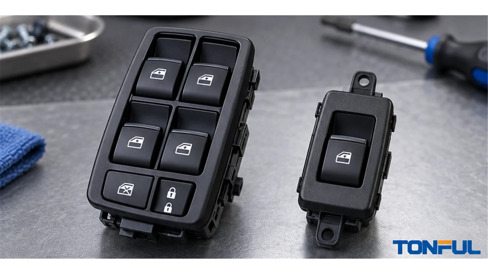
Choosing between a master and passenger power window switch should not be based on button count, housing appearance, or connector size alone. The driver master may switch motor current directly, route a passenger circuit through lockout contacts, send resistance-coded requests, or communicate with a door module. A passenger switch may be a local polarity-reversing device, a low-current request input, or a network node with its own electronics.
These differences determine whether a failed master can disable one passenger window or every window, whether the local switch remains usable, and which replacement evidence is required. Before ordering, identify the exact vehicle, market, door, LHD/RHD configuration, OE reference, connector, pinout, architecture, functions, and approved sample. No universal master or passenger pinout applies across vehicles.
On this page: Roles and Architectures | One-Touch and Anti-Pinch Boundaries | Fault Isolation and Compatibility | Sourcing and Release
Roles and Architectures
What Makes a Switch “Master” or “Passenger”?
A master switch is defined by control scope, not simply by having four rockers. It normally gives the driver authority over several windows and may include window lock, door lock, mirror selection, folding, heating, illumination, or automatic-window stages. In some systems it also distributes power, ground, or lockout paths to local switches. In others it sends only commands to a driver-door module.
A passenger switch normally controls one local window, but its electrical role depends on the system. It may reverse motor polarity locally; share current paths with the master; send a voltage or resistance request; or communicate with a local door module. Front and rear passenger switches may look alike while using different keying, illumination, lockout behavior, or terminal assignments.

Master and passenger connector size, cavity count, and mounting features must be compared with controlled pinout and application records.
Four Common Control Architectures
| Architecture | Master switch role | Passenger switch role | Main verification items |
|---|---|---|---|
| Direct polarity reversing | May carry motor current and reverse polarity through contact paths; may also route power or lockout to local controls | May reverse its local motor directly or operate through master-series contacts | Circuit and contact diagram, current path, terminal size, loaded voltage drop, contact heating, lockout path |
| Relay or BCM request | Sends a low-current voltage or ground request to relays, BCM, or door electronics | Sends an independent or shared low-current request | Request voltage, logic state, reference ground, relay/BCM input, output command, diagnostic data |
| Resistance coded | Produces a defined resistance for each rocker position, sometimes through one signal line | May use another resistor range or local coded input | Resistance window for every state, tolerance, reference circuit, connector pinout, module recognition |
| Networked door module | Sends digital commands or is integrated with a door module; may contain software | Sends commands to a local module or operates as a networked node | LIN/CAN or specified interface, hardware/software revision, coding, wake/sleep behavior, DTCs, functional matrix |
This table describes architecture categories, not a rule that every vehicle uses one pure type. A master assembly can combine direct contacts for one function, resistor coding for another, and network communication for door electronics. The vehicle wiring diagram and product specification must identify the actual paths.
Does the Master Carry Every Motor’s Current?
Not necessarily. Older or simpler systems may route substantial motor current through master and local switch contacts. In that arrangement, the master connector often contains several motor or feed paths, and worn contacts can affect a passenger window even when the passenger switch is mechanically sound. Inspection should include loaded voltage drop, heat damage, terminal retention, contact condition, and the exact lockout circuit.
Relay-, BCM-, or door-module-controlled systems can keep motor current out of the visible switches. The rocker then supplies a low-current command, resistance state, ground request, or digital message. Larger terminal count still does not prove direct motor loading because the master may integrate mirrors, locks, illumination, communication, and other signals.
Must the Passenger Command Pass Through the Master?
Only the circuit diagram can answer. In a series-contact design, passenger control may depend on master neutral contacts, feed paths, or window-lock contacts. A failed or disconnected master can therefore disable local operation. In a module-based design, master and passenger requests may travel independently to the same door module or to separate modules. A network, power, ground, or module fault may then disable both without either rocker assembly being defective.
Use the Power Window Switch Buying Guide to capture architecture and interface requirements before comparing parts. Do not infer the command route by probing unknown terminals or by assuming that wire color is consistent across model years.
One-Touch and Anti-Pinch Boundaries
Separate the Rocker Input From System Control
One-touch down may require only a second detent or timed command, while one-touch up can interact with position learning and obstacle protection. The switch may contain the decision logic, but that logic may instead reside in the motor electronics, a local door module, the master assembly, or the BCM. Replacing a rocker that clicks correctly does not prove that learned limits, current sensing, position feedback, communications, and automatic reversal are operating correctly.
If one-touch or automatic closing is included, identify whether obstacle detection, automatic reversal, current sensing, position learning, and initialization belong to the switch, motor controller, door module, or vehicle system. Approval of the switch alone does not establish compliance of the completed power-window system.
| Function | Possible responsible element | Evidence to request |
|---|---|---|
| First/second rocker stage | Switch mechanism and contacts or coded output | Force-travel curve, state output, detent and return |
| Window position learning | Motor controller, door module, master, or BCM | Vehicle procedure, learned-position data, relearn result |
| Obstacle detection | Motor-current algorithm, position/speed sensor, edge sensor, or module logic | System architecture, diagnostic data, approved vehicle test method |
| Automatic reversal | Motor controller or vehicle control logic commanding the motor | Vehicle-level result, reversal condition, fault handling |
| Initialization/relearn | Vehicle procedure and control module memory | Trigger condition, sequence, completion evidence, DTC status |
Apply FMVSS 118 at the Correct Level
The official 49 CFR §571.118 addresses vehicle-level requirements for power-operated window, partition, and roof-panel systems, including permitted closing conditions, actuation-device operation, and qualifying automatic-reversal systems. It does not by itself confirm switch interchangeability, pinout compatibility, or supplier approval.
NHTSA’s TP-118-06 laboratory test procedure is likewise organized around vehicle-system compliance testing, including actuation-device and automatic-reversal evaluations. It is not a universal incoming-inspection procedure for a loose switch. Determine whether the regulation applies to the target vehicle and market, then connect component requirements to the completed-system validation plan.
Fault Isolation and Compatibility
Use Symptoms to Select the Next Test
| Symptom | More likely fault area | Next check |
|---|---|---|
| All windows are inoperative | Main power, fuse or breaker, master feed, ground, BCM, door module, or network | Verify supply and ground under load, module communication, DTCs, and master or module outputs |
| Passenger window works from master but not locally | Passenger switch, window-lock input, local feed, ground, or wiring | Confirm lockout state and compare local switch input/output with the diagram |
| Local switch works but master cannot control that window | Master channel, master-to-module command, series contact, or communication path | Compare local and master requests at the controlled test points |
| Manual operation works but one-touch fails | Initialization, learned position, coded second stage, motor controller, or module configuration | Follow the vehicle relearn procedure and review switch states and DTCs |
| Only backlighting fails | Illumination supply, ground, polarity, LED, dimming or PWM command | Check illumination terminals and command waveform against vehicle documentation |
| Direction reverses after replacement | Wrong part version, terminal assignment, motor polarity, or coded-state interpretation | Stop operation and compare OE reference, pinout, architecture, and terminal functions |
| One door is completely offline | Door-module power/ground, connector, harness, network, or module | Check module communication and door-harness interfaces before replacing the switch |
This matrix sets a diagnostic direction, not a replacement verdict. The switch-versus-motor-versus-regulator guide helps isolate the failed system element. The How to Test a Power Window Switch article explains why testing must start with the vehicle diagram, safe access, and identified test points.
Evidence and Conflict-Control Rules
Create one controlled evidence record instead of repeating generic warnings at every step. Record vehicle and market, production range, door position, LHD/RHD, complete OE and supplier references, document revision, sample and lot ID, photographs, connector viewing direction, populated cavities, pinout source, architecture, function matrix, test conditions, results, approver, and date.
If the catalog, removed part, drawing, or test result conflicts, preserve every source and mark the application unresolved. Do not choose the source that produces the widest fitment range. Photographs should use consistent front, rear, side, label, and connector-end views, but photographs cannot establish internal contact routing or software compatibility.
Compare Connector, Pinout, and Functions Separately
Check bezel and mounting geometry, depth, clips, connector shell, keying, latch, terminal count, populated cavities, and terminal retention. A connector that mates can still have different outputs. Verify each cavity by function rather than transferring a generic pinout between vehicles.
Build a matrix covering every window, local and master control, window lock, door lock, mirror direction and selection, folding, heating, illumination, manual and AUTO stages, and communication where applicable. The OE-number verification guide explains why the number is only a search key until mechanical, electrical, and functional evidence agree.

Door position, steering configuration, mounting, connector, and complete function scope must be verified for both master and passenger switches.
Sourcing and Release
Build an RFQ Around the Actual Architecture
Send the supplier vehicle, market, model year or production range, door position, LHD/RHD, complete OE reference, removed-part photographs, connector views, pinout, circuit architecture, and function matrix. Identify whether the request is for a mechanical sample, fitment approval, electrical validation, or production release. The Power Window Switch RFQ and Sample Approval Checklist provides a controlled structure for sample identity, commercial terms, packaging, and approval status.
For direct-load designs, request evidence tied to current path, voltage drop or contact resistance, heating, terminals, and endurance conditions. For resistance-coded designs, require every position’s specified resistance window and method. For networked products, include hardware, software, coding, communication, diagnostics, sleep/wake behavior, and programming controls. Do not replace product-specific acceptance values with generic internet limits.
Control the Approved Sample and Changes
Sample approval should identify exact part and revision, application, connector, pinout, architecture, functions, test plan, deviations, and approval scope. Sample approved does not automatically mean unrestricted mass-production approval. Define receiving inspection, traceability, packaging, warranty evidence, and notification before changes to housing, contacts, plating, springs, lubricant, resistor values, PCB, software, illumination, tooling, site, sub-supplier, or test method.
The Power Window Switch Manufacturer Audit Checklist can be used when repeat-production controls require review. Approval should remain limited to the named vehicle, door, steering configuration, market, and evidence set.
Work With TONFUL
TONFUL’s automotive power window switch range presents current vehicle applications and OE reference numbers. Confirm the exact vehicle, OE reference, master or passenger position, LHD/RHD, connector, pinout, architecture, functions, approved sample, and project-specific validation plan before ordering. Motor, regulator, door-module, and completed-system compliance must be discussed separately and must not be assumed from the switch catalog.
