
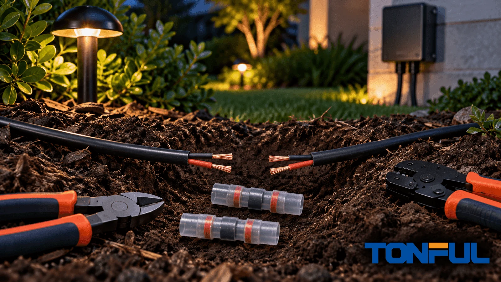
A cut underground landscape-lighting wire should be repaired with a connector system approved for the conductor combination, voltage, and burial condition. Twisting the copper together and wrapping it with ordinary tape may restore the light temporarily, but soil moisture can enter the splice and cause corrosion, resistance, intermittent operation, or another failure.
This guide applies to typical low-voltage landscape-lighting circuits. If the cable voltage, circuit source, cable type, or local requirements are uncertain, stop and use a qualified electrical or landscape-lighting professional.
Tools and Materials
- Voltage tester or meter suitable for the circuit
- Cable marker or flags
- Clean cutter and wire stripper
- Approved direct-bury waterproof connector or splice kit
- Matching replacement cable if the damaged section is too short
- Clean gloves and lint-free wipes
- Hand tools for careful excavation
- Manufacturer instructions for the selected connector
3M describes its Direct Bury Splice Kits as moisture-sealed systems used for landscape lighting, irrigation, and direct burial. Whatever brand is selected, use the complete approved system rather than loose grease, tape, or a standard indoor wire nut.
Step 1: Isolate and Verify the Circuit

Switch off and disconnect the landscape-lighting power supply according to its instructions. Confirm that the cable is de-energized before touching conductors. Do not rely only on the lighting schedule or a wall switch.
Identify both ends of the damaged circuit and confirm that the cable belongs to the low-voltage lighting system. Underground sites can contain irrigation control wire, communications cable, invisible pet fencing, and higher-voltage circuits.
Step 2: Expose Enough Clean Cable
Excavate carefully by hand around the cut. Create enough working space to inspect the cable on both sides without sharply bending it. Avoid pulling on buried sections because hidden insulation damage may extend beyond the visible cut.
Clean away soil and moisture. Inspect for:
- Crushed, stretched, or sliced insulation
- Blackened or green copper
- Missing conductor strands
- Multiple cuts from a shovel or edging tool
- Water that has traveled under the jacket
Cut back to clean, bright conductor and sound insulation. If that leaves too little slack, install a compatible replacement section with one approved splice at each end rather than forcing the original cable together under tension.
Step 3: Select the Correct Waterproof Splice

Match the connector to:
- Number of conductors in each splice
- Conductor size and solid or stranded construction
- Copper conductor compatibility
- Circuit voltage
- Wet and direct-burial location
- Cable insulation diameter
- Available space and strain relief
A connector labeled merely “weather-resistant” or “outdoor” may not be approved for burial. Review TONFUL’s direct-burial wiring guide and the exact product documentation.
For compact branch-style splices, start with TONFUL’s waterproof wire nut range. For a straight inline repair, an approved heat-shrink or direct-bury splice system may fit better. The article comparing waterproof wire nuts and heat-shrink butt connectors explains the geometry difference.
Step 4: Prepare the Conductors
Follow the connector’s specified strip length. Use a matched stripper and avoid nicking solid conductors or cutting strands from flexible wire.
If copper is corroded beyond the first cut, continue trimming until clean metal is reached. Do not sand heavily corroded conductor and hide it inside a new splice; corrosion can remain between strands.
Keep wire ends clean. Soil, water, fertilizer, and oil can interfere with contact and contaminate sealing compound.
Step 5: Install the Connector System
For a prefilled twist-on connector:
- Arrange conductors as the instructions require.
- Insert them fully into the sealant-filled shell.
- Tighten until the internal spring grips the approved bundle.
- Check that no bare copper remains outside the connector.
- Tug each conductor gently as directed by the manufacturer.
For a tube-style kit, complete the specified electrical splice and seat it fully inside the prefilled tube. Do not substitute components from another system.
Use TONFUL’s waterproof wire nut installation guidance as a general process reference, but follow the instructions supplied with the exact connector.
Step 6: Test Before Reburial
Restore power only after all conductors are enclosed and the work area is safe. Confirm that every downstream fixture operates. Check for flicker, unexpected dimming, or intermittent response while gently moving the insulated cable near the repair.
If voltage or current measurements are required, use equipment and procedures suitable for the system. A lighting circuit that still fails may have another cut, damaged fixture, overloaded transformer, poor connection, or cable-voltage-drop problem.
Disconnect power again before final handling if the repair needs repositioning.
Step 7: Protect and Rebury the Repair
Place the splice according to the connector and cable instructions. Avoid sharp stones, standing tension, tight bends, or a location where edging tools routinely cut the soil. Restore the required burial depth and mark or document the repair location for future service.
Do not encase an unapproved connector in improvised sealant as a substitute for a listed splice system. Extra material can hide installation defects and complicate future inspection.
Common Repair Mistakes
| Mistake | Why it fails |
|---|---|
| Ordinary wire nut plus tape | Neither component may be approved as a direct-bury sealed system |
| Splicing corroded copper | Corrosion remains inside the electrical contact |
| Stretching cable to reach | Tension transfers to the splice and wire entries |
| Guessing wire size | Connector spring or barrel may not retain the conductor correctly |
| Reusing a filled connector | Sealant distribution and gripping parts may be compromised |
| Burying before testing | A second excavation is required if the repair is wrong |
TONFUL’s guide to visually inspecting waterproof wire nuts provides additional rejection signs.
Diagnose Before Cutting More Cable
A visible cut may not be the only fault. Before removing cable, document which fixtures are dark, dim, or intermittent and where the damaged point sits relative to the transformer and branches. A fault affecting every light suggests checking the source, timer, breaker, transformer output, and main run first. A fault beginning after one excavation point makes the damaged cable or splice more likely. One failed fixture may indicate a local lamp, socket, lead, or branch problem instead.
With the circuit isolated, inspect both conductors for abrasion and moisture travel. After a safe temporary measurement setup is established, compare source voltage with voltage at accessible downstream points under the normal lighting load. An unloaded voltage reading can look acceptable even when a high-resistance splice causes substantial drop in service. Use equipment appropriate to the circuit and keep exposed test points protected from soil and water.
| Symptom | First evidence | Next decision |
|---|---|---|
| All fixtures off | Source status and transformer output | Repair supply issue before opening buried splices |
| Fixtures after cut are off | Cable route, continuity with power isolated | Expose and assess damaged section |
| Downstream fixtures dim | Loaded voltage at source and load | Check conductor loss, overload, and high-resistance joints |
| Lights flicker when soil moves | Cable and splice movement test | Locate damaged insulation or unstable contact |
| New repair works briefly | Connector approval, copper condition, water path | Remove contaminated conductor and rebuild correctly |
Decide Between One Splice and an Extension Section
Use one inline repair only when both cable ends reach the approved connector without tension, sharp bending, or exposed damaged insulation. Add a compatible replacement section when excavation removed slack, corrosion has traveled along the conductor, or equipment movement would load the joint. This creates two splice locations, so both must remain accessible or be approved for the intended burial condition and documented on the site plan.
The replacement cable must match the system requirements for conductor material, gauge, insulation, polarity identification, voltage, temperature, and burial use. Do not insert a smaller conductor merely because it fits the connector. A smaller section can add voltage drop and may not match the circuit protection or equipment instructions. Maintain polarity or conductor identification consistently through both joints.
Commission and Record the Repair
Testing should prove more than “the lamp turns on.” Record the transformer tap or output condition, circuit load, voltage at a repeatable upstream point, voltage at the repaired branch, and operation of every downstream fixture. Compare the result with the lighting manufacturer’s instructions and the project’s approved voltage-drop allowance. Do not publish a universal acceptable value because cable length, conductor size, transformer design, load, and system voltage differ.
Inspect the splice while the circuit operates normally. There should be no flicker when the insulated cable is moved gently, no exposed copper, no strain at the wire entry, and no enclosure interference. De-energize again before final positioning. Photograph the completed joint, record connector part and lot where practical, mark the repair on the cable route, and note the date and technician.
Prevent the Next Excavation Damage
Restore the cable route according to local requirements and the equipment instructions. Route away from edging lines, stakes, drainage work, and planting holes where possible. Use approved mechanical protection where the design requires it, but do not trap water around an incompatible splice. A warning marker or updated as-built drawing is often more useful than an improvised hard cover that later conceals the cable.
For commercial properties, add the repair to preventive maintenance. Inspect after landscaping changes, flooding, repeated breaker or transformer trips, or reports of intermittent dimming. Repeated damage at the same area indicates a routing or work-control problem, not simply a connector problem.
Frequently Asked Questions
Can I use electrical tape underground?
Tape alone is not a substitute for a connector system approved for the electrical splice and burial condition.
What if the cable has no slack?
Add a compatible section of cable and make two approved waterproof splices. Do not leave the original cable under tension.
Can I repair line-voltage outdoor lighting this way?
This guide is written for typical low-voltage landscape lighting. Line-voltage work has different hazards and requirements; use a qualified electrician and approved materials.
Build a Repair That Can Stay Buried
The durable repair is clean, mechanically secure, electrically verified, sealed with an approved system, and installed without cable strain. Share the wire size, voltage, conductor count, and burial environment with TONFUL to identify a candidate waterproof connector and request product documentation.
