
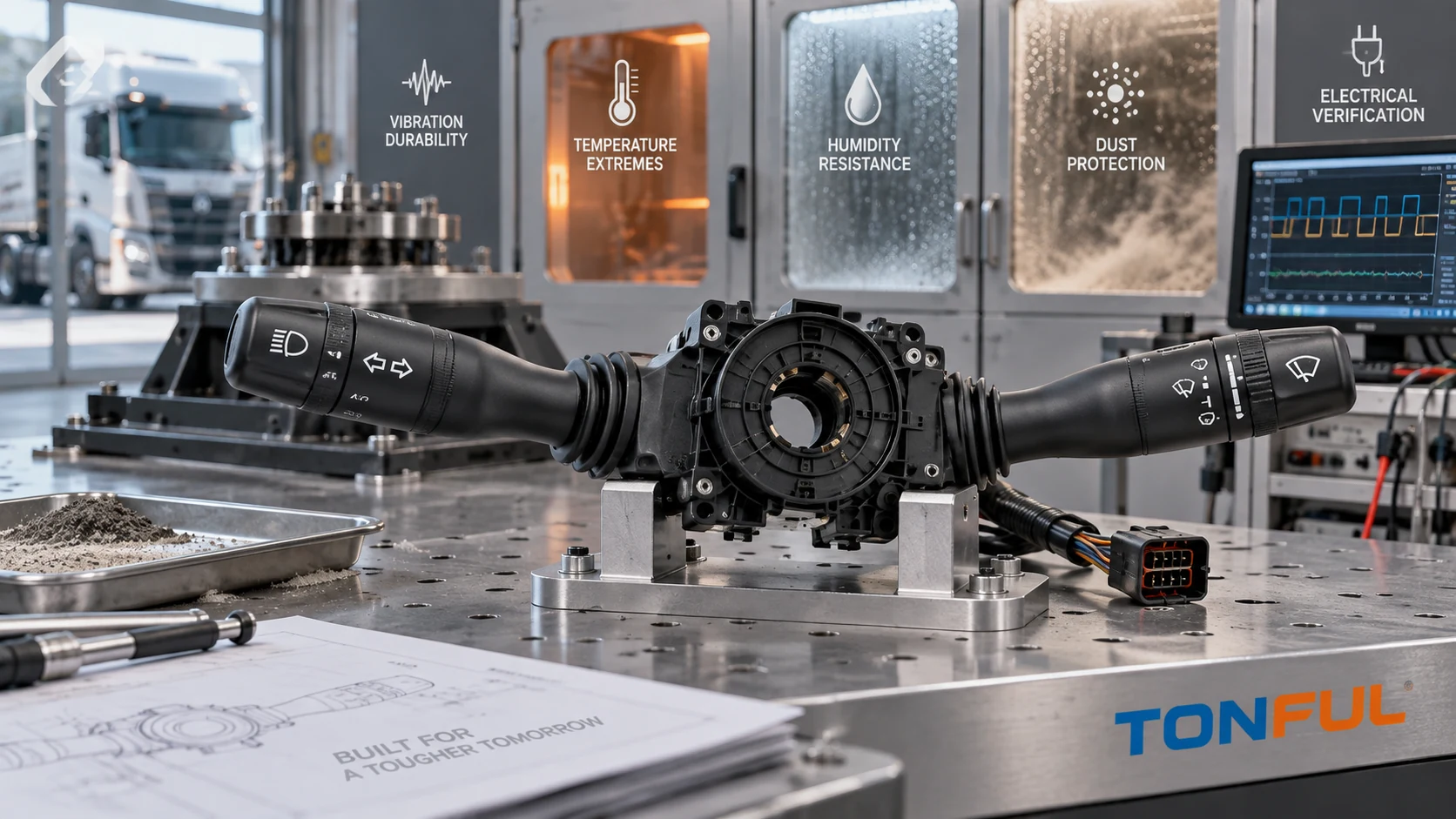
A heavy-duty truck combination switch should not be released from a generic “automotive grade” statement. The steering-column location exposes the assembly to driver cycling, column vibration, cab shock, temperature change, humidity, dust, cleaning chemicals and electrical disturbances. The relevant severity also changes with cab design, mounting stiffness, market, duty cycle and whether the stalk contains simple contacts, a resistor network or electronics.
A useful environmental test plan therefore begins with the application and failure risks, then defines samples, test sequence, measurements and acceptance sources. It does not copy one severity from another vehicle or claim compliance merely because a laboratory used an ISO method.
On this page: Define the Mission Profile | Build the Test Matrix | Control Samples and Sequence | Release Evidence
Define the Mission Profile
Establish Product and Installation Boundaries
Record the truck family, market, production range, 12 V or 24 V architecture, LHD/RHD configuration, steering-column mounting, connector and harness restraint. Define every stalk function: turn signal, headlamp request, high-beam flash, wiper/washer states, cruise controls, horn or menu inputs where fitted. The heavy-duty truck combination switch selection guide explains why vehicle and OE scope must be fixed before validation.
Identify the electrical architecture. A direct-load contact, relay-coil output, resistance-coded input and LIN/CAN steering-column module have different electrical stresses and failure evidence. Document supply domains, current paths, wake/sleep states, loads, protection, software and diagnostic behavior. “24 V truck” does not mean every switch terminal operates at 24 V.
Map foreseeable field stresses to failure modes. Column vibration can fret terminals or crack solder joints; repeated cab shock can loosen mechanisms; heat can change lubricant, plastics and resistor values; condensation can promote leakage or corrosion; dust can obstruct detents; chemicals can attack legends; and electrical disturbances can reset or damage electronics. This risk map should connect the design FMEA, qualification plan and production control plan.
Use Standards as Frameworks, Not Product Claims
ISO 16750-3:2023 describes mechanical loads for road-vehicle electrical and electronic equipment, while ISO 16750-4:2023 describes climatic loads. Their scope is tied to potential stresses and the component’s mounting location. Neither official summary supplies a universal truck-stalk severity, sample count or acceptance limit.
The project must identify the applicable edition, test method, mounting category, severity, duration, operating mode and acceptance criteria from customer/OEM requirements or an approved qualification plan. Passing a selected method supports only the tested configuration and conditions; it does not establish blanket compliance for every truck.
Build the Test Matrix
Mechanical, Climatic and Contamination Tests
| Test family | Configuration to define | Measurements before/during/after | Combination-switch failure evidence |
|---|---|---|---|
| Random/sine vibration | Vehicle axes, fixture, spectrum, duration, powered state | Contact interruptions, communication, torque, visual condition | Intermittent output, terminal fretting, PCB or bracket damage |
| Mechanical shock | Pulse, axes, count, fixture and operating mode | Functional monitoring and post-test dimensions | Cracked housing, shifted cancel mechanism, lost detent |
| Temperature operation/storage | Min/max, ramp, dwell, powered states | Function matrix, force-travel, voltage drop/resistance | Binding, drift, weak return, display/communication fault |
| Thermal cycling/shock | Transfer or ramp, dwell, cycles | Leakage, insulation, function and visual evidence | Seal pumping, condensation, solder or interface damage |
| Humidity/condensation | Profile, bias, recovery and orientation | Leakage, coded states, corrosion and insulation | False requests, resistance drift, corrosion residue |
| Dust | Dust type, pressure, operating motion and orientation | Detents, rotary movement, contact output | Abrasion, blocked mechanism, contamination |
| Fluids/chemicals | Named fluid, concentration, application, temperature | Legend, polymer, force and electrical condition | Swelling, cracking, erased symbol, lubricant loss |
The fixture must reproduce production mounting and connector support without adding unrealistic stiffness. Route and restrain the harness as installed. For vibration, monitor circuits likely to reveal micro-interruptions rather than relying only on a final continuity check. Define interruption threshold and acquisition bandwidth from the approved plan, not from a blog.
Temperature testing should exercise all maintained and momentary states at specified checkpoints. Measure operating force, return, detent definition, contact voltage drop or coded output, communication and illumination as applicable. A room-temperature pass after recovery can conceal a cold bind or hot resistance drift.
Dust and fluid tests need explicit product orientation and exposure boundaries. A column switch is not automatically an exterior sealed device. If ingress protection is claimed, define the exact housing, mating connector, seals, mounting condition and applicable method. Do not convert a material splash test into an IP rating.
Electrical and Functional Stress
Electrical validation should reflect the architecture and vehicle supply profile. Define normal range, cranking/brownout, overvoltage, reverse polarity, interruptions, ground offset, load dump or other transients only where applicable. For electronic switches, record current consumption, reset behavior, communication recovery, stored DTCs and unintended outputs. For contact switches, use the approved load type, inrush, switching sequence and protection.
The 12 V versus 24 V combination switch guide provides the required domain-by-domain comparison. The LED versus incandescent load guide explains why nominal lamp wattage alone cannot define contact stress.
Environmental exposure and endurance are related but not interchangeable. A separate mechanical/loaded endurance program should represent the function sequence and cycling rate. Environmental tests can be combined with operation when the plan requires it, but the report must state whether the sample was energized, switched or dormant during each period.
Post-Exposure Verification
Use the same controlled baseline and final methods. Check housing, legends, connector, terminals, mounting, stalk play, detents, return, self-cancel interface and every function. Measure force-travel, contact voltage drop or resistance-coded windows, insulation/leakage, illumination and network behavior where applicable. Preserve DTC and waveform evidence before clearing faults.
Destructive analysis may include housing opening, terminal/contact inspection, solder examination or cross-sectioning when the risk plan requires it. Destructive results belong to identified samples and locations; they do not replace functional evidence from the whole group.

Link each environmental exposure to a controlled configuration, measurement and product-specific acceptance source.
Control Samples and Sequence
Create a Sample Allocation Plan
| Record field | Required entry |
|---|---|
| Product identity | Part number, revision, software, lot and build date |
| Sample identity | Unique ID and photograph set |
| Production intent | Materials, tooling, process and deviations |
| Test group | Exposure sequence and control/reference samples |
| Preconditioning | Storage, stabilization and initial cycling |
| Fixture/harness | Drawing revision, connector, wire and restraint |
| Equipment | Model, range, accuracy and calibration status |
| Operating state | Powered, loaded, switched, monitored or dormant |
| Acceptance source | Drawing/specification/approved plan and revision |
| Invalid/retest rule | Preapproved handling of fixture or equipment failures |
| Disposition | Pass, fail, conditional or engineering review |
Sample quantity must come from the qualification plan and confidence required; do not choose it after seeing results. Retain unexposed controls when material drift or measurement repeatability needs comparison. Document production-intent status and every deviation because hand-built samples may not represent molded dimensions, plating, lubrication, soldering or final assembly.
Sequence Tests Deliberately
A single sequential group can reveal accumulated damage, but it may make the initiating stress difficult to isolate. Independent groups improve attribution but do not show interactions. A balanced plan often uses dedicated groups for severe or destructive exposures plus one sequence representing field ageing. The rationale belongs in the plan.
Record initial measurements, exposure checkpoints and final measurements. If conditioning changes moisture content or temperature, define stabilization before measurement. Do not retest a failed sample until it passes without preserving the first result and investigating the cause. A fixture failure may justify an invalid test only under the preapproved rule and with objective evidence.
The combination switch mechanical endurance guide provides a complementary cycle-record structure. Keep qualification, design investigation and production monitoring distinct: they use different sampling and decision rules.
Investigate Failures to Root Cause
Quarantine the affected sample and related build lot. Preserve logs, DTCs, waveforms, photographs and test conditions. Confirm whether the event came from the product, fixture, harness, load, chamber or acquisition system. Then localize it through visual inspection, connector checks, function-state testing, electrical measurement and teardown.
An intermittent circuit after vibration may originate at the contact, crimp, terminal interface, solder joint or harness strain point. A sticky stalk after cold exposure may involve dimensions, polymer contraction, lubricant or water. Corrective action should update the drawing, process, PFMEA, control plan or test method as appropriate, followed by justified confirmation testing.

Preserve sample identity and compare post-exposure function, mechanics and electrical evidence with the approved baseline.
Release Evidence
Use a Traceable Results Matrix
| Sample/Test | Requirement source | Initial result | Exposure evidence | Final result | Failure mode | Disposition |
|---|---|---|---|---|---|---|
| Enter ID and method | Document/revision/clause | Controlled value | Log/file/photo ID | Controlled value/change | None or observed mode | Pass/Fail/Review |
A pass requires all mandatory acceptance criteria, not an average that hides one failed sample. Any permitted deviation must identify the product scope, reason, risk owner, expiry and closure evidence. An untested function or environment remains unverified; it cannot be recorded as compliant.
Release records should include the approved plan, sample genealogy, fixtures, equipment, raw data, calculations, photographs, software, anomalies, failure analysis, corrective action and signed conclusion. Link these records to the exact drawing and change level.
Final Approval Checklist
- Vehicle, mounting location, voltage domains and functional architecture are defined.
- Customer/OEM requirements and applicable standard editions are controlled.
- Risks connect to test groups, methods and measurable acceptance criteria.
- Samples are production-intent, uniquely identified and properly allocated.
- Fixtures reproduce mounting and harness support without masking failures.
- Tests specify axes, profiles, durations, fluids, operating modes and monitoring.
- Baseline, during-test and final measurements use controlled methods.
- Failures, invalid tests, retests and deviations follow preapproved rules.
- Reports preserve raw evidence and define the exact approved scope.
- Design/process changes trigger documented impact review and requalification.
Work With TONFUL
TONFUL’s automotive combination switch range provides current product references for sourcing discussions. Share the vehicle/OE scope, mounting arrangement, circuit architecture, environmental specification, required test sequence and acceptance-source documents. TONFUL can review product evidence and sample requirements against the defined project; environmental performance should be stated only for the exact tested configuration and conditions.