
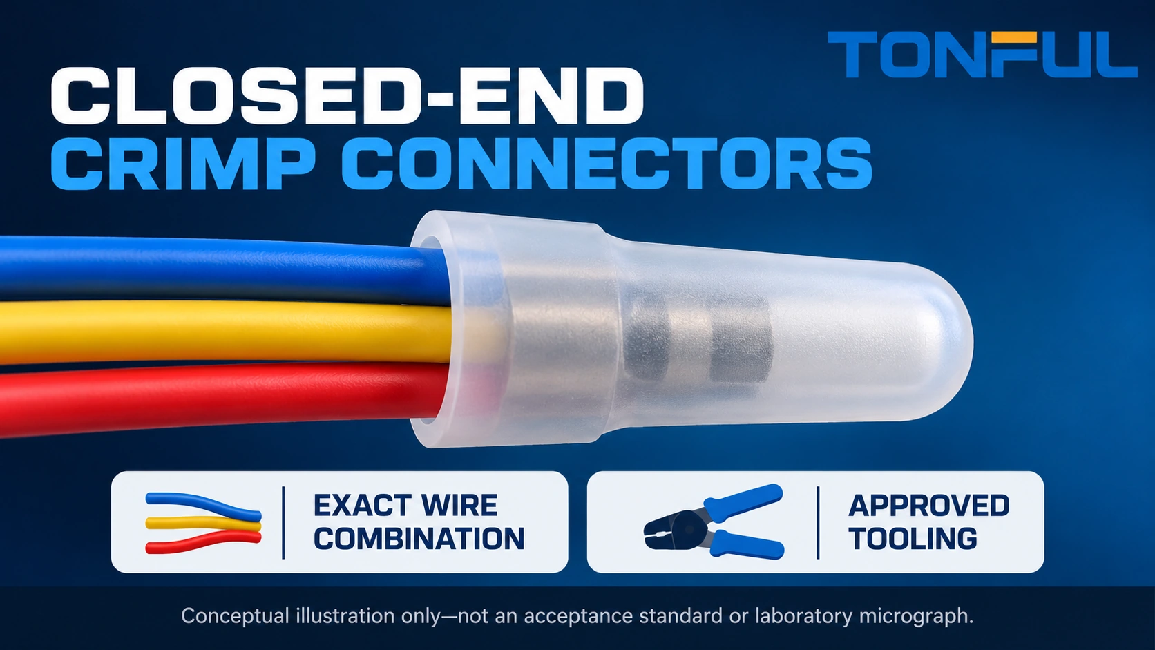
Closed-end crimp connectors combine or terminate wire ends inside a crimped connector body, with the wires entering from the same side. Selection depends on the exact conductor combination and approved tool process, not merely on whether a bundle fits through the insulation opening. A small conductor can remain inadequately captured even when the larger wires appear secure.
For production, release a connector, wire combination and tooling instruction together. The records below help engineering and purchasing define that configuration without inventing a universal wire-count chart. They also identify when a closed-end joint is the wrong architecture, particularly where repeated disconnection, environmental sealing or special repair authorization is required.
Jump to: Identify the connector architecture | Approve the wire combination | Specify the tooling system | Control preparation and insertion | Validate and record the joint | Release and source responsibly
Identify the Connector Architecture
Distinguish a crimp cap from neighboring products
A closed-end crimp connector is not a twist-on wire connector and is not an end-to-end butt splice. Its metal termination region is compressed by the specified tool, while the closed covering arrangement contains the wire ends. The actual internal construction and permitted preparation depend on the selected part; do not infer them from a generic cap outline.
The official Molex closed-end connector overview identifies closed-end products for capping or combining wire ends. That supports the architecture distinction, not any particular TONFUL wire combination, environmental protection or rating. Obtain the actual part drawing and application instruction for the proposed joint.
Begin a supplier discussion with the TONFUL terminal product scope and describe the required same-side wire entry. Ask for the proposed closed-end part identity rather than accepting an unmarked assortment. If the requirement is instead a branch splice with a different conductor arrangement, resolve the architecture before selecting the tool.
Decide whether a permanent joint is appropriate
Closed-end crimps are generally treated as permanent terminations, not reusable disconnects. A service plan that requires frequent separation may need an approved disconnectable system. Do not assume that cutting away the cap leaves enough undamaged wire for unlimited future repairs; harness length, routing and repair instructions constrain that decision.
Do not describe a closed plastic end as proof of a sealed connection. Water can enter around wire exits unless the complete product and installation provide documented protection. Specify exposure, temperature, vibration and enclosure needs so engineering can determine whether an unsealed cap is suitable or another approved solution is needed.
Approve the Wire Combination
Use an exact configuration schedule
List each conductor separately by wire identity, material, nominal area or AWG, strand construction and insulation diameter. Include quantity of each wire and how the wires enter the connector. The connector’s general wire range does not necessarily approve every possible mixture of sizes and counts within that range.
Adding nominal conductor areas can describe the bundle but is not sufficient sizing authority. Strand arrangement, material, barrel geometry and die compression affect capture. Two combinations with the same area sum may behave differently. Require the connector supplier’s exact permitted combination or an engineering-approved qualification route for the actual configuration.
| Combination field | Required entry | Why it matters |
|---|---|---|
| Connector identity | Supplier part and drawing revision | Defines the actual barrel and cap |
| Wire identities | Separate part references for every variant | Prevents nominal-size substitutions |
| Quantity and arrangement | Count and entry arrangement | Defines the intended population |
| Conductor construction | Material, strand form and finish | Affects compression and compatibility |
| Insulation envelope | Diameter and material by wire | Affects entry and support |
| Authorization | Combination document or approved evaluation | Establishes permission to proceed |
Protect the smallest conductor
An assembly can appear solid while a small wire sits outside the effective compression region. Keep every wire identified through preparation and insertion, especially where the combination mixes sizes. Validation should address retention of each relevant conductor, not only a pull on the largest wire or the complete bundle.
Do not fold a small wire, add spare strands or prefill the barrel to imitate a larger conductor unless the governing instruction explicitly permits that method. Do not apply a sizing factor taken from a different splice architecture. This article does not apply a NASA multi-wire butt-splice rule to closed-end caps; the governing product and application documents decide the combination.

Specify the Tooling System
Match the die to the connector body
Record the tool model, die, cavity, locator where applicable and instruction revision. A tool that can physically compress the cap is not necessarily suitable for the metal barrel inside it. The selected process must form the intended conductor crimp without damaging the covering or leaving a conductor outside the controlled region.
When reviewing TONFUL crimping tools, share the proposed connector and exact wire schedule. Request the documented match and setup information. Sleeve color or a generic wire-range marking is not enough to establish cavity compatibility across different terminal designs.
Define the process before buying volume
State hand-tool, bench-tool or automated assembly needs and the expected packaging format. Determine whether the tool completes the specified cycle consistently and how setup is verified. Clarify maintenance, wear inspection and calibration requirements where applicable. A tool substitution should pass the same authorization route as a connector substitution.
For a new combination, agree the development evidence before ordering production. Define which samples represent limiting wire constructions, insulation sizes and expected process variation. Record sample preparation and actual tooling settings so successful development work can be transferred to the production instruction rather than recreated from operator memory.
Control Preparation and Insertion
Preserve every conductor during stripping
Use the specified strip length and preparation method. Inspect for cut or missing strands, nicked conductors and insulation remnants in the intended metal crimp zone. Keep stripped wires identified so a correct-size bundle is not assembled with the wrong circuit or wire construction. Do not trim away an inconvenient strand to make insertion easier.
Align the wire ends according to the approved instruction. Do not assume that pre-twisting is required, harmless or forbidden for all products; follow the actual process document. The goal is controlled capture of the approved conductors, not a visually tidy bundle created by an improvised operation.
Verify seating before compression
Ensure that all intended conductors reach the specified termination region and that insulation has not displaced a small wire from it. Where the covering prevents direct observation, use the product’s approved insertion verification and process controls. Do not invent a universal exposed-copper length or use force to compensate for an overfilled entry.
Hold the bundle in the prescribed position through the crimp cycle. After release, inspect cap damage, misplaced crimp location, loose wires and exposed conductor against the applicable criteria. Insulation appearance alone cannot confirm the metal termination inside. Stop and quarantine uncertain joints instead of adding another crimp in an unapproved location.
Validate and Record the Joint
Separate verification from informal handling
Use the agreed plan for sample quantity, wire combinations, preparation, conditioning and acceptance sources. Mechanical testing needs a defined fixture, pull direction, speed, equipment range and accuracy. State how each conductor is evaluated and how invalid tests, grip slips and retests are handled. No universal pull force is assigned here.
Electrical evaluation, where required, should define test current, Force/Sense probe locations, reference-wire lengths, offset correction or forward/reverse measurement and ambient temperature. Record reference-wire resistance subtraction where applicable. For a multi-wire node, identify the measured branch pair; a low result between two large wires does not establish the condition of a small branch.
| Release record | Fields to complete |
|---|---|
| Configuration | Connector revision, wire identities and exact counts |
| Process | Tool, die, cavity, preparation and instruction revision |
| Samples | Quantity, selection rationale, lots and conditioning |
| Mechanical evidence | Individual conductor, fixture, method, result and failure mode |
| Electrical evidence | Branch pair, current, probes, temperature and correction method |
| Acceptance | Governing document, criterion and reviewer |
| Disposition | Release, restriction, containment or further work |

Keep damage evidence and change history
Record the condition after testing, including conductor pull-out, strand breakage, connector damage and fixture problems. A result outside criteria needs a documented disposition, not an automatic repeat until a passing number appears. Where destructive sectioning is required, define section location and acceptance reference before interpreting it.
Renew review when wire construction, connector source, barrel design, tooling or preparation changes. Keep the validated population distinct from unsampled alternatives. A previously accepted pair of wires does not authorize an additional branch simply because the new bundle enters the cap.
Use a combination-change log alongside the bill of materials. This is particularly useful when purchasing consolidates several harness variants into one connector stock item. A common cap part number does not erase differences in its approved wire populations.
| Proposed change | Required review before implementation |
|---|---|
| Add or remove a branch | Exact new count, arrangement and combination authorization |
| Change a wire supplier | Actual construction and insulation differences, not gauge alone |
| Change the tool cavity | New process match and evidence representing the revised setup |
| Change cap source | Drawing, barrel, covering and application-instruction comparison |
Record the affected harness variants, reviewer and implementation lot. Keep old and new instructions separated at the line so the change does not create an uncontrolled mix of wire counts or process settings.
Release and Source Responsibly
Keep alternative terminal families in their proper roles
Review nylon-insulated terminal families for covered termination discussions, and non-insulated terminals where a separately designed insulation system is appropriate. Do not infer identical crimp processes or environmental performance across these families. Require a specific part proposal before making a substitution.
Similarly, cord end terminals serve compatible clamp interfaces and are not substitutes for a closed-end multi-wire splice. Bundling wires in a ferrule and covering its end does not create an approved crimp cap. Keep the selected connection architecture visible on the harness drawing and bill of materials.
Establish safe implementation boundaries
Assemble and service only safely de-energized equipment using the site’s authorized isolation procedures. Do not use this guide to splice live wiring or bypass equipment repair rules. Automotive restraint, traction, protective and other safety-critical functions require the relevant system owner’s approved process; a generic cap is not a universal repair part.
Send TONFUL the exact wire combination schedule, application conditions, installation envelope and expected tooling method when requesting samples. Ask for the proposed connector drawing, authorized combination and supporting process information. Release only the configuration supported by your engineering review and validation record, not a general wire-count assumption.