
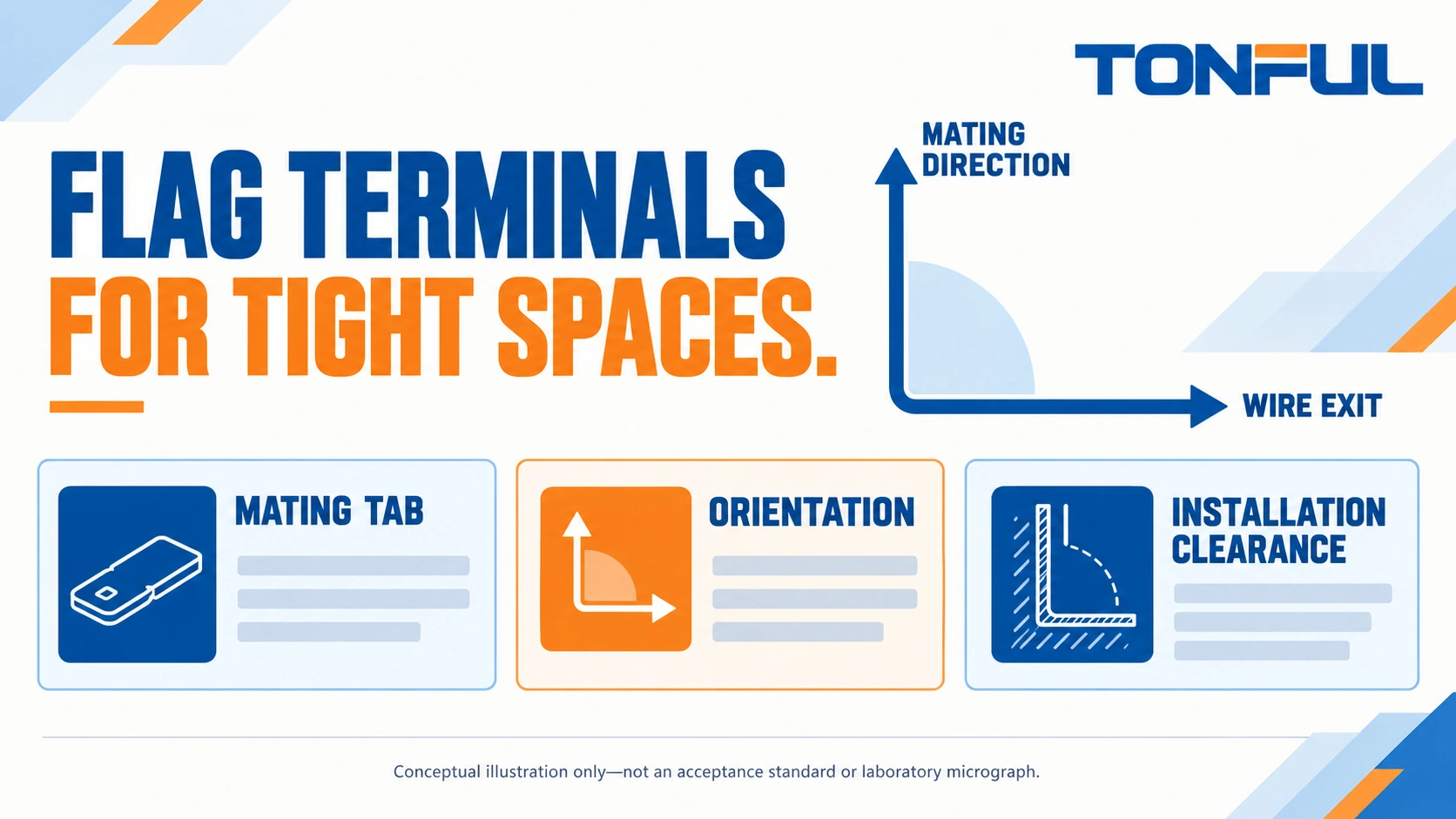
Flag terminals for tight spaces redirect the wire exit relative to the mating direction, helping a harness fit where a straight receptacle may project into a cover or adjacent component. That geometry solves only one part of the problem. The receptacle must still match the tab, protect the connection and allow assembly and service without forcing the wire or terminal into position.
Select a flag terminal from the complete installed arrangement: mating tab, receptacle, wire barrel, insulation, routing and access. The review record below helps engineers and buyers compare proposed parts without treating a nominal tab width or a photograph as proof of fit. All dimensions and acceptance criteria must come from the actual drawings and application instructions.
Jump to: Define the flag orientation | Match the mating tab | Review the installed envelope | Choose wire and tooling | Complete the assembly review | Source and service safely
Define the Flag Orientation
Name the axes instead of relying on a photograph
A flag receptacle is a quick-disconnect form with a right-angle wire-exit arrangement relative to its mating axis. Describe the mating direction, wire-exit direction and orientation around the tab using a drawing or controlled view. Terms such as “left flag” are ambiguous unless the viewing direction is defined.
The official TE FASTON terminal overview distinguishes straight and flag styles and tab width and thickness. That is useful selection context, not proof that similarly named parts from different suppliers interchange. Use the chosen receptacle’s drawing and application specification to establish the permitted mating interface.
Start a sourcing conversation through the TONFUL terminal product range with an installed-view sketch. Show where the wire must travel after mating, which face is accessible and where neighboring conductors sit. Ask for a proposed part drawing rather than approving a catalog image viewed from an uncertain angle.
Do not make a flag by bending another terminal
If a straight receptacle conflicts with the available space, do not bend its barrel or contact body to imitate a flag unless the product instructions explicitly authorize that operation. Deformation can alter mating geometry, insulation and the wire transition. Select an approved right-angle form or redesign the routing with engineering authorization.
Check whether the flag arrangement genuinely improves the assembly. A lower projection above the tab can come with a wider side envelope or different access needs. The correct choice may be a straight terminal with revised routing or a different connector architecture, rather than the smallest-looking flag in a catalog.
Match the Mating Tab
Width and thickness are separate requirements
Record tab width, thickness, usable engagement length and relevant retention feature. A common nominal width does not establish the correct thickness range. Mismatched thickness can prevent proper engagement or alter contact behavior. Do not squeeze the receptacle or file the tab to correct an unapproved pair.
Include the tab supplier part number and drawing revision when available. Check how the tab is supported by the equipment; its attachment must not be used as a lever during mating. Identify whether the receptacle uses friction retention, a dimple or another feature, and whether a release action is required during service.
| Interface characteristic | Required evidence | Question to resolve |
|---|---|---|
| Tab width | Tab and receptacle drawing limits | Is the intended series correct? |
| Tab thickness | Approved mating thickness | Is this receptacle variant appropriate? |
| Engagement length | Functional contact and seating information | Can full engagement occur? |
| Retention feature | Matching feature and instruction | How is seating and retention verified? |
| Surface system | Approved material and finish pairing | Is a substitution technically reviewed? |
| Support and access | Equipment installation drawing | Can mating occur without damage? |
Distinguish a trial fit from approval
A sample sliding onto a tab is useful evidence, but not a complete qualification. Compare drawing tolerances and the selected pair’s instructions. When an alternative supplier proposes a different geometry, document the difference and the evaluation needed. Do not transfer the incumbent’s approval merely because the first sample feels similar.
Inspect the tab for deformation, damage or contamination before evaluating a new receptacle. A worn service tab can distort the apparent fit of a correct replacement, while a damaged receptacle can affect an otherwise acceptable tab. Retain identities and condition notes so the decision is based on the intended parts rather than an unknown field sample.

Review the Installed Envelope
Include the barrel, sleeve and wire bend
The relevant envelope is the completed termination, not just the metal receptacle body. Include sleeve thickness, barrel position, wire outside diameter and the space required to route the wire without an abrupt bend at its exit. Use the wire manufacturer’s routing constraints and the equipment requirements rather than inventing a universal bend radius.
Review nylon-insulated terminal families for covered construction discussions. Do not assume that a sleeve eliminates all accessible conductive surfaces or provides a seal. For non-insulated terminal options, define the separate insulation and protection arrangement before accepting the installation envelope.
Check assembly space and service space separately
The installer may need room to grip the body, align the contact and complete mating. A service technician may need additional access to a retention release or protective cover. Mark these spaces on the layout rather than assuming that the final static outline proves the part can be assembled or removed.
Consider adjacent tabs, screws, enclosure walls and harness branches. A flag wire exit can cross a neighboring connection even if the receptacle itself fits. Check movement and tolerances with the equipment closed, including covers and barriers. Do not rely on compressing a wire bundle against a cover to maintain clearance.
Choose Wire and Tooling
Match the conductor barrel independently
Specify wire material, nominal area or AWG, strand construction, conductor finish where relevant and insulation diameter. A receptacle that mates to the tab may still have the wrong barrel for the wire. Select a variant covering both requirements rather than inserting a small wire into an oversized barrel to obtain the desired tab interface.
Do not assume a multi-wire termination is permitted. Require the exact combination and approved process if several conductors share a barrel. A cord end terminal is a different termination for an approved receiving clamp, not a substitute for a flag receptacle. Keep interface names precise when purchasing across several terminal families.
Confirm tool access without deforming the flag
Record terminal, wire, tool, die, cavity, locator and instruction revision. Flag geometry can affect terminal positioning and tool access; do not assume that a tool used for a straight receptacle works on the right-angle variant. The functional mating portion must remain undamaged through the crimp operation.
Discuss the actual part with the TONFUL crimping tools team before choosing tooling. Ask how the terminal is located, how wire insertion is maintained and which inspections verify the finished crimp. A general tool-range marking is not an application-specific approval. Preserve setup and tool-change verification records for production.
Complete the Assembly Review
Use one record for fit and implementation
The following template is an editorial review aid, not an inspection certificate. Attach controlled drawing views and actual evidence. Engineering should distinguish approved fit, unresolved questions and conditional restrictions. Keep the wire, tool and mating tab identities in the same record so later substitutions cannot silently separate them.
| Review block | Required entry | Stop or escalate when |
|---|---|---|
| Mating pair | Tab and receptacle parts/revisions | Compatibility lacks a documented basis |
| Orientation | Defined view, mating axis and wire exit | Installed direction remains ambiguous |
| Static envelope | Body, insulation, wire and tolerances | Interference or protection gap remains |
| Assembly access | Grip and mating route | Installation needs bending or force |
| Service access | Release and removal route | Removal requires pulling the wire |
| Crimp process | Wire and tooling configuration | Tool or combination is unapproved |
| Validation | Plan, samples, criteria and results | Evidence does not represent production |
| Release | Reviewer, restrictions and changes | Open technical decisions remain |

Define meaningful verification
Check full seating, correct retention operation, wire routing and insulation condition using the approved instruction. Do not judge mating solely from an audible click or sleeve position unless the product defines that indication. Inspect the functional contact after any assembly difficulty, and quarantine a part requiring adjustment outside the instructions.
If mechanical validation is required, distinguish wire-crimp pull from mating retention. Specify sample quantity, conditioning, fixture, alignment, equipment range and accuracy, speed, invalid-test handling and acceptance document. Do not assign one universal pull force to all flag terminals. Record failure mode and location, not just a peak value.
For required electrical evaluation, define current, Force/Sense positions, reference-wire lengths, temperature and offset compensation or forward/reverse measurement. Subtract reference-wire resistance where the approved method calls for it. Keep initial and aged conditions comparable. A continuity indication is not evidence that temperature rise or resistance under the specified load is acceptable.
Source and Service Safely
Send an installed-view RFQ
Provide the supplier with tab drawings, required flag orientation, wire specification, protective covering needs and the assembly/service envelope. Ask for the proposed terminal drawing, matching tooling and any exceptions. Request samples that represent the intended production configuration, not hand-adjusted pieces that fit only the development fixture.
Agree packaging that protects formed geometry and maintains lot identity. Mixed variants with similar sleeves should remain distinguishable through receiving and line feeding. Control changes in terminal, tab, wire, tooling and insulation through the engineering release process. A commercial substitute should not bypass the interface review.
Resolve layout conflicts by naming the failed review, rather than simply requesting a smaller part. A cover interference is an installed-envelope issue; an inaccessible retention release is a service-access issue; an obstructed tool locator is a termination-process issue. Each may need a different solution. Record whether the agreed correction changes the connector, the harness route, the cover or the assembly sequence, then update the relevant drawing instead of leaving the solution as a workshop instruction.
Keep disconnected equipment genuinely isolated
Perform assembly and service only after safe de-energization and verification under authorized equipment procedures. A quick disconnect is not automatically a load-break device. Do not use this guide to improvise repairs in traction, restraint or other safety-critical circuits; the system owner’s approved methods take precedence.
Send TONFUL the installed-view sketch, tab requirements and complete wire data when requesting a flag-terminal proposal. Ask for a documented mating and tooling recommendation, then approve the full termination envelope before production. That keeps the space-saving decision tied to compatibility, controlled assembly and safe future service.