
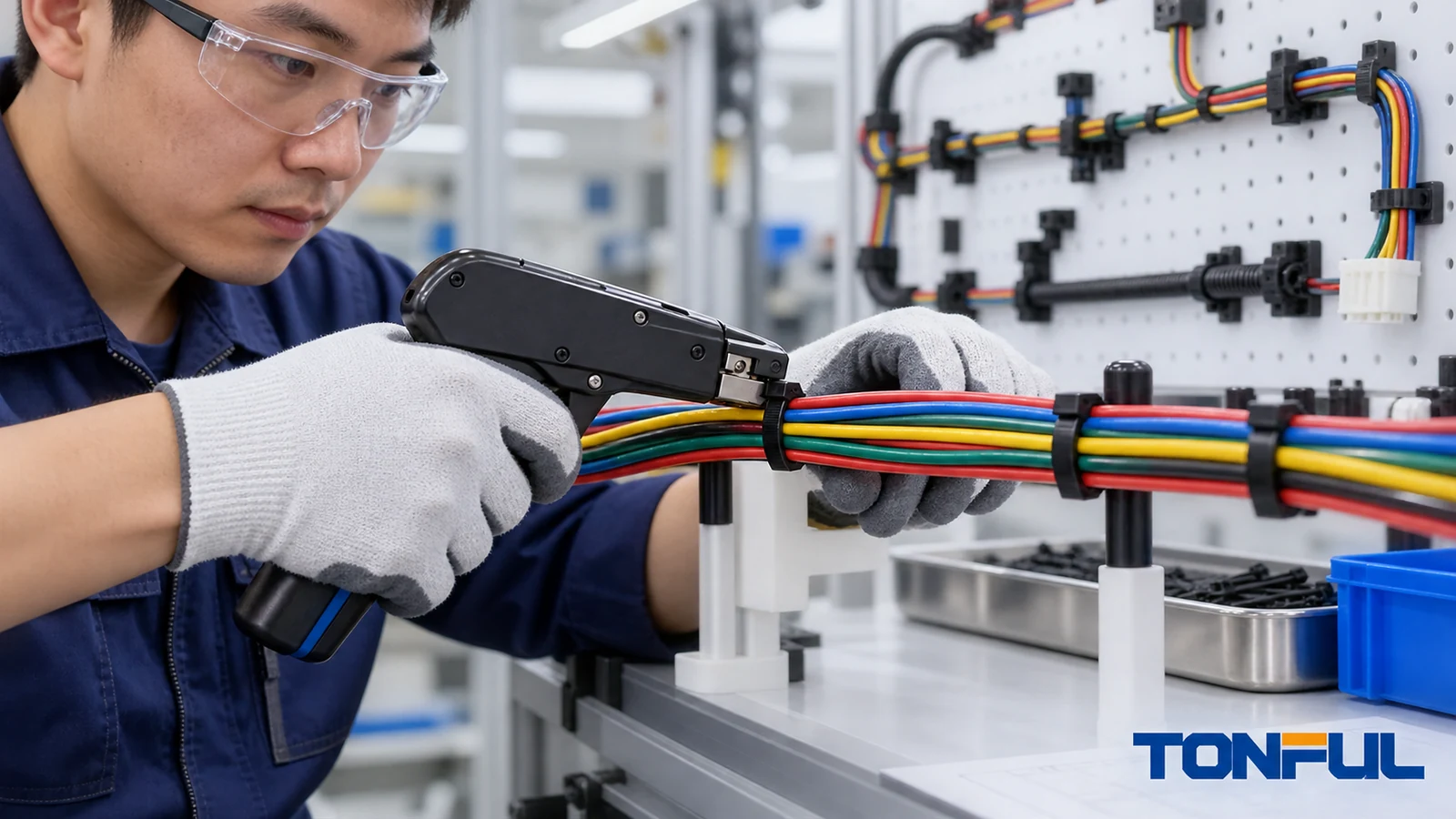
A cable tie should be tight enough to maintain the approved route and prevent unwanted relative movement, but not so tight that it indents, flattens, cuts or otherwise damages the cable jacket. There is no universal hand-pull force or tool number for every bundle. The correct installation tension depends on the tie, cable construction, bundle geometry, environment, motion and customer specification.
That answer is more useful than “pull it as tight as possible.” Maximum tightness can concentrate pressure under a narrow strap, deform sensitive cables and load a connector. Too little tension can let wires slide, vibrate against an edge or escape a routing feature. The goal is controlled restraint, not maximum force. A validated tool setting, first-piece inspection and documented acceptance criteria make the result repeatable.
Installation Tension Is Not Loop Tensile Strength
Installation tension is the force used to cinch a tie around the bundle before its tail is cut. Minimum loop tensile strength is a separate product characteristic measured by loading a closed tie under a defined test. A tie can have a high loop-tensile value and still be installed too tightly around a delicate cable. Conversely, a low tool setting does not prove that the final route can withstand vibration or pull.
The TONFUL minimum-loop-tensile guide explains that property boundary. For installation, control the interaction among tie width, strap stiffness, head geometry, bundle diameter and cable-jacket response. Do not use a catalog tensile number as the tension-tool setting, and do not convert it into an allowable clamp pressure.
| Quantity | What it describes | Main control |
|---|---|---|
| Installation tension | Force used to tighten the strap | Validated tool/method and first-piece inspection |
| Bundle pressure | Local compression transferred to cables | Tie width, geometry, cable construction and tension |
| Loop tensile strength | Defined mechanical property of the closed tie | Product test method and specification |
| Retention in service | Ability to maintain route under actual conditions | Complete installation and environmental validation |
| Support capacity | Ability of approved assembly to carry cable weight | Tie, fixing, fastener, substrate and governing rules |
What “Correctly Tightened” Looks Like
The tie should lie flat and remain fully engaged in its head. The bundle should stay in the drawing-defined position when subjected to the permitted handling or service check. Individual wires should not be visibly flattened, pinched, kinked or forced across a sharp edge. The head should not create an abrupt bend, and the trimmed tail should not abrade adjacent insulation. Where the design permits small internal movement, do not eliminate it simply because a tighter bundle looks neater.
A visual “finger test” can be a useful screening observation but not a universal acceptance method. Wire diameter, jacket hardness and bundle construction change what feels snug. Some specifications may allow limited tie rotation or require a defined clearance; others may require a tool-controlled setting. Use the applicable drawing, work instruction and cable manufacturer’s limits. If those documents do not define acceptance, engineering should establish it using representative samples before production.

Signs of Too Little Tension
- The tie or bundle can migrate out of its approved location.
- Wires rub against a bracket, enclosure edge or moving part during the specified motion check.
- The bundle changes shape enough to load connectors or violate clearance.
- A mount or clip cannot control the route because the strap remains loose.
- The tail or head shows incomplete engagement or improper tool use.
These observations do not justify pulling every tie harder. A tie may be the wrong length, width, head type or mounting design. The route may need another support point. First confirm the tie’s intended role using the TONFUL cable-tie application guide.
Signs of Excessive Tension
- Visible indentation, flattening, whitening or cutting of insulation.
- Distortion of coaxial, data, fiber-optic or pneumatic components.
- A tie head pressed into a cable or located on a tight bend.
- Wires unable to move as required for thermal expansion or service.
- Strap, teeth or head damage caused during installation.
- Changed electrical, optical or pressure performance after bundling.
Damage can develop over time even when the initial appearance seems acceptable. Sustained pressure, heat and vibration can aggravate deformation or abrasion. A high-risk cable may require a wider tie, protective separator, different fastener or a less compressive bundling method.
Cable Construction Changes the Answer
Ordinary insulated hookup wires, shielded cable, coaxial cable, twisted-pair data cable, fiber and hoses do not tolerate the same pressure. A small tie around a mixed bundle can concentrate force on the largest or softest component. A hard object under the strap, such as a splice or label edge, can create a local pressure point. Identify every bundle component rather than approving tension from overall diameter alone.
NASA’s application notes for certain AS22759 wire constructions warn against tight stitches and tie wraps where fluoropolymer insulation is susceptible to cold flow. This is a construction-specific caution, not a claim that every fluoropolymer wire or every cable tie will fail. It illustrates why the cable specification and system owner’s workmanship rules must control the installation.
For data and fiber routes, follow the cable/system manufacturer’s bend, crush and performance requirements. For power conductors, consider conductor heat, insulation temperature and permitted movement. For vehicle harnesses, include vibration, door or seat motion and connector strain. For outdoor bundles, consider UV and thermal cycling. The TONFUL outdoor cable-tie life guide explains why environment can change long-term behavior even when initial tension is correct.
Set the Tension With a Controlled Process
A hand pull varies with installer strength, posture, access and the amount of tail available. Repeatable production normally benefits from a compatible tensioning/cutoff tool. HellermannTyton’s EVO7 instructions describe selecting and locking a tension setting, positioning the nosepiece at the tie head, tensioning and cutting, and calibrating the tool. Those instructions apply to the named tool family; use the current manual and compatible tie for the actual job.
Establish a Setting
- Define the wire/cable constructions, bundle range, tie SKU, route and environment.
- Review the drawing, customer workmanship requirement and cable limits.
- Build representative bundles at the minimum, nominal and maximum geometry.
- Apply candidate settings with the intended production tool, nosepiece and blade.
- Inspect tie engagement, jacket condition, routing and tail cut.
- Perform required movement, vibration, thermal, electrical or optical checks.
- Approve a setting or bounded range and record the evidence source.
- Lock or otherwise control the tool setting, then train authorized operators.
Do not copy a numbered dial position from another tool. Dial values may not be force units, and wear or calibration can change output. A setting validated on a wide tie around robust power cable may not be suitable for a narrow tie around small signal wires. If the same station handles multiple products, use a controlled setup sheet and mistake-proofing so the correct tie and setting are selected.
Verify the Tool
Record tool ID, model, compatible tie range, setting, calibration/verification status, blade condition and inspection frequency. Challenge the process after blade or nosepiece replacement, tool repair, dropped-tool event, tie supplier/material change or product revision. A flush tail cut depends on blade condition and tool alignment, while bundle pressure depends on tension control. Both need inspection.
The TONFUL cable-tie manufacturing guide describes how dimensions and locking features originate in production. Incoming variation in strap thickness, teeth or head geometry can affect installation; do not compensate for a changed tie by quietly increasing tool tension.
First-Piece and Production Inspection
At the beginning of a run, after setup change and at defined intervals, inspect a representative first piece. Record bundle part/revision, tie lot, tool ID and setting. Check the head orientation, tie position, jacket condition, routing, required movement and cut tail. Where the plan requires destructive sectioning or functional testing, allocate samples before production begins rather than choosing them after a concern appears.
| Inspection field | Evidence | Reaction if unacceptable |
|---|---|---|
| Tie identity | SKU, material, dimensions and lot | Stop and segregate wrong material |
| Tool setup | Tool ID, controlled setting and verification | Correct setup; reassess affected work |
| Bundle geometry | Minimum/nominal/maximum sample | Revalidate if outside approved range |
| Jacket condition | No prohibited indentation, cut or flattening | Quarantine and assess cable damage |
| Route retention | Approved movement/handling result | Correct route or support design |
| Head and tail | Position, engagement and flush cut | Repair process/tool before continuation |
| Functional evidence | Required electrical/optical/mechanical checks | Follow nonconformance plan |
Operators should not use “one more click” as an undocumented correction. If a tie is loose after the approved cycle, investigate tie selection, bundle range, tool operation and route. Cutting off and replacing a tie can itself damage wires; use the controlled method in the TONFUL cable-tie removal guide. Record suspect serial/lot boundaries so inspection does not depend on memory.
Troubleshooting Bundle Damage or Slippage
When insulation shows marks, first contain the affected work. Compare tie SKU, lot, tool ID and settings with an accepted sample. Inspect for a worn blade, damaged nosepiece, incorrect tie width, doubled cable, hidden splice or edge under the strap. Determine whether the mark was present before tying. Evaluate the cable under its approved acceptance or repair procedure; do not hide a questionable cut beneath a new tie.
For slippage, distinguish strap looseness from a moving mount, flexible bundle or wrong support spacing. Check locking-head engagement and whether contamination affected the tie. Verify that thermal cycling or vibration did not change the route. Increasing tension may worsen cable damage without fixing a weak mount. The TONFUL edge-clip cable-tie guide illustrates why mounting geometry must be assessed separately.
Corrective action should update PFMEA/control plan or equivalent documents where relevant: the failure mode, cause, prevention, detection, owner and effectiveness check. Retrain operators only when the evidence identifies a training gap. Material, design or tool problems require their own permanent actions.

A Copyable Approval Record
| Record field | Required entry |
|---|---|
| Bundle/application | Product, route, function and risk |
| Cable construction | Part numbers, jacket materials and diameter range |
| Tie | Manufacturer, SKU, lot, width and material |
| Tool | Model, ID, nosepiece/blade and status |
| Candidate settings | Samples built and actual settings tried |
| Visual findings | Indentation, flattening, head, tail and route |
| Functional checks | Motion, electrical, optical or environmental results |
| Approved control | Setting/range, work instruction and inspection frequency |
| Change triggers | Cable, tie, tool, route, supplier or environment changes |
| Authorization | Engineer/quality approver and date |
This record prevents a tool number from becoming an unexplained tribal rule. It links the setting to the bundle, tie and evidence. If any controlling input changes, engineering can identify what must be reverified rather than assuming the old setting remains valid.
Work With TONFUL
Send TONFUL the cable constructions, bundle-diameter range, environment, tie function, installation tool and customer acceptance criteria. Request exact-product drawings, samples and lot identification. TONFUL can help compare tie widths, lengths, materials and head styles, but should not prescribe one universal tension for an unknown harness. Final release belongs to the controlled application: a named tie, representative bundle, validated tool setting and documented inspection plan.
Technical Sources
- HellermannTyton EVO7/EVO7SP operating instructions: example of adjustable, lockable and calibratable installation-tool tension; apply the current tool-specific manual.
- NASA NEPP AS22759 wire application notes: construction-specific warning concerning tight ties and cold flow in susceptible fluoropolymer insulation; not a universal cable-tie tension limit.