
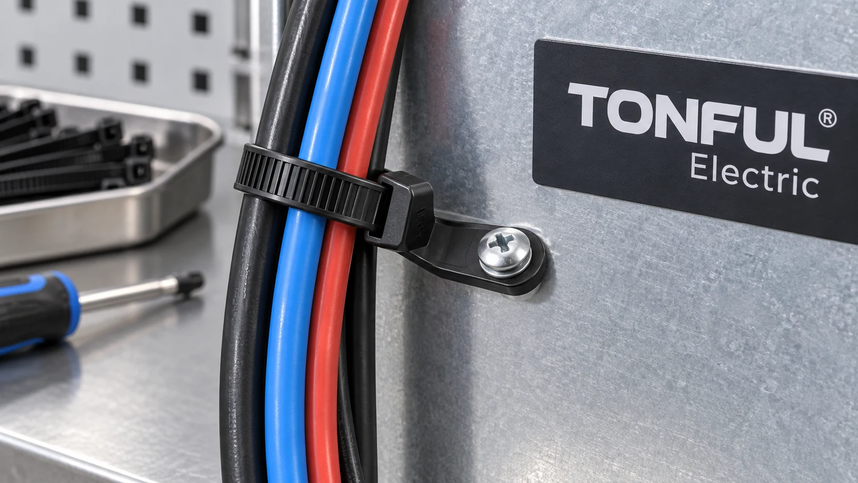
A mountable-head cable tie combines a strap and a fastening lug with a hole for a screw or bolt. It can secure a bundle to a panel without a separate cable-tie base, but only if the hole, fastener, panel and cable route work as an assembly. A tie with a strong loop can still detach when its lug cracks, screw loosens or substrate strips.
This guide covers the integrated screw-hole type. It is not the same as an arrowhead or fir-tree foot pushed directly into a panel hole, and it is not the same as a plain tie threaded through a separate screw-on base. The TONFUL push-mount comparison addresses the snap-in alternatives. Here the key interface is the screw-fastened lug.
Understand the Integrated Mounting Head
The mounting head is a molded extension of the tie head or strap with a through-hole. A screw or bolt clamps the lug to a panel, bracket or other approved substrate. Depending on design, the installer may fix the empty tie first and then place the bundle, or prebundle the cables and fasten the assembly afterward. The chosen order affects tool access and risk of twisting the lug.
HellermannTyton’s mounting-head catalogue describes one-piece ties with built-in holes for screw fixing. Its individual T30MR example lists a mounting screw type, bundle range, loop tensile strength and a distinct mechanical-strength field. Those details belong to that model. They demonstrate why buyers need separate evidence for the loop and the lug, not a universal TONFUL size or load value.
Obtain a dimensioned drawing with lug hole diameter, outer width, thickness, distance from hole center to strap/head, clearance around the fastener head and overall projection. A catalogue photo cannot reveal whether the screw head bears fully on the lug or whether a washer interferes with strap movement. The lug’s orientation relative to the tie loop determines whether cable weight produces shear, peel or torque at the fixing.
| Component | Function | Failure to prevent |
|---|---|---|
| Strap and locking head | Retain cable bundle | Slip, fracture or jacket damage |
| Molded lug | Transfer bundle force toward fastener | Cracking, creep or hole elongation |
| Screw/bolt and washer | Clamp lug to substrate | Loosening, pull-through or crushing |
| Threaded hole or nut | Hold fastener | Stripping or loss of preload |
| Panel/bracket | Carry installed load | Bending, cracking or corrosion |
Match Lug Hole to the Fastener System
The lug hole must fit the specified screw or bolt without excessive clearance or forcing. A nominal M4 or #8 description is not enough: check actual shank diameter, thread form, head or washer diameter and the lug’s available bearing area. A small head may pull through or locally indent the polymer. An oversized washer may collide with the tie head or prevent full seating on a curved panel.
Specify the fastener material and coating for the location. A steel screw in an outdoor bracket needs a corrosion review; a stainless fastener with another metal substrate may introduce galvanic considerations. For a plastic boss, thread design and pilot hole matter. For sheet metal, decide whether the connection uses a tapped hole, self-tapping screw, insert, rivet nut or through-bolt. Each has a different failure mode and rework rule.
Torque is not determined by tie width. The correct value must account for screw, thread, substrate, washer and polymer lug. Excessive torque can crack or creep the lug; insufficient clamp may allow rotation and fretting. Request a project-approved tightening method and torque/angle or other control where needed. After torqueing, inspect the lug for distortion and verify that the tie can still be threaded and tightened as intended.
| Fastener field | Required entry |
|---|---|
| Lug | Hole diameter/tolerance, thickness and bearing area |
| Screw/bolt | Size, thread, length, material and coating |
| Head/washer | Contact diameter and approved washer type |
| Substrate | Material, thickness, hole/thread method and condition |
| Installation | Tool, seating, tightening requirement and access |
| Service | Removal/reuse rule, replacement fastener and inspection |

Conceptual load path; the drawing does not assign a load rating or tightening torque.
Check the Panel and Routing Geometry
Record where the cable bundle sits relative to the mounting hole. If the strap head is offset, the bundle may apply a moment to the lug. A vertical wall mounting differs from a horizontal shelf: gravity, vehicle acceleration, vibration and service pulls change direction. Confirm clearance to sharp edges, moving components, terminals and inspection access.
The panel itself can be the weak point. Thin sheet metal may deform under a concentrated load; a molded boss can crack; a threaded insert can loosen. Paint, gasket material or uneven bracket surfaces may prevent the lug from seating flat. Use actual production surfaces and coating thickness in fitment trials. If the mount is intended to act as a stand-off, verify the cable-to-panel gap at the worst-case bundle diameter and after aging.
Do not route cable weight through an unsupported connector. Provide slack and strain relief between the mounting tie and any plug or terminal. The TONFUL cable-tie applications guide distinguishes bundling, positioning and support. State which role the mounted tie performs. If a fixing is primary support, obtain product-specific and installation-specific approval rather than assuming a screw automatically makes the tie load-bearing.
For a panel without an allowed screw hole, an edge clip or push-in foot may be more suitable. The TONFUL edge-clip guide covers a flange interface; it has its own thickness and retention limits. Do not drill a new vehicle body or enclosure hole without design approval because it can affect corrosion protection, sealing and nearby systems.
Separate Loop Strength From Mount Strength
A loop-tensile test loads the closed strap in a defined fixture. It does not automatically include lug bending, screw clamp, substrate pull-out or vibration. The TONFUL tensile-strength guide explains this boundary. Some manufacturers publish separate mechanical strength and loop tensile fields for a mounting-head part, confirming that one number should not be substituted for the other.
The installed load path is: cable bundle to strap, strap to locking head and molded lug, lug to screw or washer, fastener to thread or nut, and finally into the panel or bracket. The lowest reliable capacity along this path governs the assembly, but the service load is not necessarily a simple static weight. Lateral pull, thermal cycling and repeated service can reduce margin. Define the direction and duty before selecting a part.
For electrical installations, UL’s cable-tie application guidance distinguishes products evaluated for securing from those suitable for support and addresses fixing-device markings. It does not certify a TONFUL mounting-head tie, fastener or substrate by association. Check exact model coverage and package markings when a recognized or listed product is required.
| Claim | Evidence needed | Common wrong inference |
|---|---|---|
| Declared loop tensile strength | Tie size, condition, test method and result | Same value is installed support load |
| Lug retention | Head/washer contact and pull direction | Screw size alone proves capacity |
| Panel attachment | Thread or insert, torque and substrate test | Metal panel cannot fail |
| Vibration durability | Actual route, fastener and aging sequence | One static pull is enough |
| Outdoor suitability | Exact tie, screw and panel corrosion/UV evidence | Black strap is outdoor-rated |
Select Material for the Location
The strap and lug may share one polymer in a one-piece design, but they experience different stress. The loop flexes during installation; the lug stays clamped and can creep under long-term load or heat. A PA66 tie may need controlled storage and conditioning before installation. The TONFUL nylon storage guide addresses handling; it does not qualify the lug for an engine bay, outdoor cabinet or chemical washdown.
Specify actual temperature, fluids, sunlight, humidity and expected service period. Heat-stabilized or UV-stabilized material names are not complete performance claims. Ask whether the exact color, material grade and mounting-head geometry were tested together. If the screw or washer changes, evaluate whether the new contact pressure causes cracking or loss of clamp over time.
Avoid assuming that a stainless screw makes the entire assembly corrosion-proof. The substrate, coating and washer are part of the system. Water trapped between a flat polymer lug and metal panel can affect the panel surface, while a loose fastener can abrade coating under vibration. If sealing is needed, specify a tested seal design; a bare mounting head is not an IP-rated cable entry.
Install Without Damaging the Lug or Cable
Define a repeatable sequence. Confirm the correct part and fastener, prepare the approved hole, seat the lug flat, tighten by the specified method, then loop and tension the strap without dragging it across the fastener edge. In some assemblies prebundling is necessary; if so, check that the installed bundle does not twist the lug during tightening. Do not clamp the strap under the screw unless the design explicitly requires it.
Inspect for lug cracking, washer misalignment, fastener bottoming, incomplete thread engagement, cable-jacket indentation and sharp cut tails. Record the installation tool and setting. If a tie must be replaced, determine whether the screw, insert or threaded hole can be reused. A new strap attached to a stripped boss will not restore the original load path.
The receiving and first-piece check should compare lug hole, head geometry and strap dimensions with the controlled drawing. Mold flash around the hole can prevent seating; a short shot can thin the lug. Production lot and cavity traceability help investigate repeated cracks. The TONFUL manufacturing guide covers molding control principles for nylon ties.
Test the Complete Installed Assembly
Build samples on production-intent panels and fasteners at tolerance extremes. A qualification plan should state sample counts, orientation, temperature, conditioning, tightening method, fixture, pull direction, rate and acceptance source. Test static retention only where it represents the real load. Add vibration, thermal cycling, fluid or corrosion exposure if the application needs them. After exposure, inspect both the tie and mounting hardware.
Separate failure modes in the report: strap break, pawl slip, lug crack, hole elongation, screw loosening, thread pull-out, panel damage and cable-jacket abrasion. A single “pass” field hides the interface that needs improvement. Retest a corrective action on production-intent samples with the same fastener and substrate. If a washer improves lug retention but creates a clearance issue, the design is not fully released.
Use this record template:
| Record field | Required entry |
|---|---|
| Identity | Tie part/revision, resin/color/lot, fastener and substrate revision |
| Geometry | Lug hole, washer/head, panel hole, stack and route offset |
| Installation | Sequence, tool, tightening result and strap tension setting |
| Baseline | Visual seating, bundle size and initial retention |
| Exposure | Temperature, vibration, fluid or aging plan and sample allocation |
| Final result | Load direction, measured result, first failure and damage photo |
| Decision | Drawing/specification limit, pass/fail, reviewer and date |

Illustrative assembly inspection; no generic screw torque or support rating is implied.
RFQ and Release With TONFUL
Send TONFUL the bundle drawing, mounting location, panel material and thickness, screw or bolt system, route offset, environment and required support function. Ask which cable tie constructions have an integrated mounting head and request exact drawings and production-intent samples. Do not infer current TONFUL availability or compliance from a competitor example.
Approve the exact tie, fastener, washer and substrate as one configuration. Record the allowed tool and installation sequence; require review when any of these interfaces changes. A mountable head saves a separate base only when the complete assembly remains secure, serviceable and compatible with the cable route.