
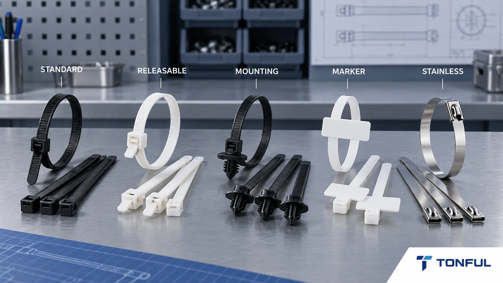
Cable ties share a basic purpose, but their head design, strap, locking method, mounting interface and material can make them unsuitable for one another’s applications. A standard nylon tie may organize an indoor harness, while an edge clip positions a bundle on sheet metal, a marker tie carries identification and a stainless steel tie addresses environments beyond a polymer design.
This guide compares five practical cable-tie families for engineers, distributors and procurement teams. Selection must still use the exact product drawing, application environment, installation method and approved evidence; a family name does not establish strength, temperature, UV life, chemical resistance or compliance.
Quick Type Comparison
| Type | Primary purpose | Defining feature | Main verification |
|---|---|---|---|
| Standard | Permanent general bundling | One-piece ratchet and pawl | Bundle range, strength method and installation tension |
| Releasable | Temporary or serviceable routing | User-accessible release feature | Reuse cycles, retained lock and operator access |
| Mounting | Position bundle relative to structure | Integral or separate fixing interface | Hole/edge/fastener geometry and retention |
| Marker | Bundle and identify | Integrated label area or identification carrier | Print durability, readability and traceability logic |
| Stainless steel | Harsh environment or higher mechanical demand | Metal strap and lock | Alloy, lock, edge condition, corrosion and tooling |
IEC 62275 covers metallic, non-metallic and composite cable ties and associated fixing devices for management and support of wiring systems in electrical installations. It does not mean every tie of one visual type has identical classifications. Verify the applicable edition, product evidence and installation requirement.
Why Similar-Looking Types Are Not Interchangeable
Two ties can share the same nominal length and color while behaving differently in assembly. Head geometry controls insertion direction and engagement; strap thickness changes flexibility around small bundles; tooth pitch affects adjustment; and the tail shape influences automated or gloved installation. A mounting feature also transfers load into a panel rather than only around the bundle. For that reason, a substitution review should compare controlled drawings instead of accepting a catalog-family match.
Create a side-by-side record for the approved part and candidate. Include overall and usable length, minimum and maximum bundle range, strap width and thickness, head envelope, locking direction, material designation, mounting dimensions, installation tool, packaging and traceability. Record any product-specific strength or environmental evidence together with its test method and conditioning. Do not compare isolated headline values measured by different methods.
When the tie interacts with insulation, hose, painted metal or a sharp panel edge, approve it in the assembled condition. Check routing clearance, contact pressure, tail trimming, nearby connector service and movement under vibration or handling. A candidate that locks successfully on a bench can still create abrasion, noise, interference or difficult maintenance after installation.
Standard Self-Locking Cable Ties
Where They Fit
Standard one-piece ties use molded teeth and a pawl in the head to form a permanent loop. They suit controlled bundling in equipment, harness production, packaging and general wire management when the material and environment are appropriate.
Select by usable bundle diameter, strap width and thickness, head envelope, locking direction, tail length and the required test property. Nominal length alone is insufficient. A tie can be long enough to close but too stiff for a small bundle, too wide for routing space or incompatible with the installation tool.
The cable ties buying guide provides the complete material-size-strength workflow. Standard does not mean universal: PA66 moisture condition, UV stabilization, colorant, temperature and chemical exposure still require evidence.
Main Risks
Over-tightening can mark insulation and restrict movement; low tension can permit abrasion or noise. A cut tail can leave a sharp edge. Mold fill, tooth form, pawl engagement and contamination can influence lock performance. Standard ties are normally removed by cutting, so service procedures must protect conductors underneath.
Releasable and Reusable Cable Ties
Release Is a Designed Function
Releasable ties add a tab, lever or head geometry that lets a user disengage the pawl. They are useful for prototypes, temporary routing, staged assembly and installations where cables are added or removed. They should not be treated as an unlimited-life version of a standard tie.
Specify who releases the tie, access direction, gloves or tools, expected cycle count and the required retained function after reuse. Inspect tooth wear, pawl deformation, strap damage and loss of holding force. The releasable cable ties guide explains why cycle life and final locking requirements must come from product-specific evidence.
Do not reuse a tie after contamination, heat exposure, excessive deformation or an unknown service history merely because the mechanism opens. For controlled production, define whether released ties return to stock, remain with one assembly or are discarded.
Mounting Cable Ties and Fixing Devices
Integral Mounting Designs
Push-mount, fir-tree, edge-clip and mountable-head ties combine bundling with positioning. The interface may enter a round hole, grip a panel edge, accept a screw or connect to a separate base. Each design converts panel geometry and installation direction into part of the product requirement.
Record hole diameter and thickness, panel edge thickness, insertion direction, available backside clearance, bundle offset, rotation control and removal method. Verify insertion force and retention under the approved panel condition. Paint, burrs, coatings, curved edges and repeated installation can change performance.
The push-mount versus fir-tree guide compares two automotive interfaces, while the edge-clip guide covers panel-edge selection. Do not replace one with another based only on bundle size.
Screw Mounts and Adhesive Bases
Mountable-head ties may use a fastener through an eyelet. Confirm fastener size, washer/contact area, tightening method, substrate and corrosion pairing. Adhesive bases require surface preparation, compatible substrate, installation pressure, cure/settling time and environmental aging evidence. Adhesive performance cannot be inferred from the tie’s tensile property.
Marker Cable Ties
Identification Is a System
Marker ties include a flag or plate for handwriting, printing, laser marking or a supplied label. They can reduce separate labels, but the identification method must survive the same handling and environment as the bundle.
Define the required characters, barcode or human-readable content, print process, contrast, abrasion, solvents, UV exposure and inspection. State whether the mark identifies a wire, harness, asset, inspection status or lot. A color or handwritten note is not traceability unless the coding rule, author and record link are controlled.
Check plate size, orientation after installation, scanning distance, obstruction and service visibility. The custom printed cable ties guide covers print and tracking decisions. Avoid placing a marker plate where it can abrade adjacent insulation or interfere with connectors.
Stainless Steel Cable Ties
Material and Locking Boundaries
Stainless ties are selected for temperature, corrosion, fire, UV or mechanical conditions beyond a polymer product’s documented capability. Common choices include 304 and 316 grades, coated or uncoated straps and ball-lock or other locking designs. These terms do not establish universal performance.
Verify alloy evidence, dimensions, lock construction, edge treatment, coating material, corrosion environment, galvanic interaction and installation tool. The 304 versus 316 guide explains why coastal exposure and material pairing matter.
Metal straps can concentrate pressure and conduct heat or electricity. Use approved protective coating, cushion or routing controls where needed. Confirm cut-tail management and worker safety. A higher loop strength does not permit unrestricted tightening around soft cables or hoses.

Conceptual type comparison only; verify the exact product drawing, material and application evidence.
Choose the Correct Type
Start With Function, Then Environment
Use this order:
- Define whether the tie bundles, positions, identifies or supports under an applicable requirement.
- Establish bundle range, routing space and mounting interface.
- Record maintenance and release needs.
- Select material for temperature, UV, moisture, chemicals, corrosion and fire context.
- Define strength, installation tension and tool controls.
- Review product evidence and production-intent samples.
One assembly may use different types at different locations. A releasable tie can support temporary build stages while a permanent mount controls final routing. A marker tie may identify only one branch. Stainless steel may be justified near a hot zone but unnecessary elsewhere.
Copyable Selection Record
| Field | Required entry |
|---|---|
| Tie function | Bundle, position, mount, identify or specified support |
| Design family | Standard, releasable, mounting, marker or stainless |
| Bundle and space | Minimum/maximum diameter, clearance and head orientation |
| Interface | Hole, edge, screw, adhesive base or no mounting feature |
| Material | Exact polymer compound or stainless grade/coating |
| Environment | Temperature profile, UV, water, chemicals, vibration and fire context |
| Strength and installation | Test method, conditioning, tension and tool |
| Maintenance | Permanent, planned release or replacement rule |
| Evidence | Drawing, datasheet, test report, sample, lot and approver |

Compare the complete head, strap, mounting interface and service requirement rather than selecting from appearance alone.
Receiving and Change Control
For bulk purchases, inspect label, lot, material designation, size, color, head and mounting geometry, packaging condition and representative locking function. Keep approved samples or controlled images. Segregate mixed or damaged bags and investigate brittle handling, incomplete molding, damaged teeth, sharp edges or inconsistent release action.
Require change notification for resin or alloy, stabilizer, color, coating, mold/tool, head geometry, locking element, mounting interface, manufacturing site, test method and packaging where relevant. A supplier SKU that remains unchanged does not prove the construction is unchanged.
Approve Production-Intent Samples
Use samples made with the intended material, tooling and process rather than appearance prototypes. Allocate enough samples to inspect dimensions and locking action, run the project-defined mechanical or environmental checks and retain an untested reference. If a test is destructive, identify the sample before testing and preserve the failed part for review. Define how invalid tests, replacement samples and retests are authorized so an unfavorable result is not silently discarded.
Approval should identify the exact part number, revision, material, color, packaging, manufacturing site, evidence reviewed and application boundary. A standard tie approved for one indoor enclosure does not automatically approve the same family for an engine compartment, outdoor installation or panel-mount location. Any later change that affects those controlled characteristics should trigger documented review and, where risk requires, renewed sample testing.
Work With TONFUL
TONFUL’s cable tie range presents standard, reusable, marker, mounting, edge-clip, fir-tree and stainless families. Send the bundle range, mounting interface, environment, serviceability, strength evidence, installation method, quantity and packaging requirements. TONFUL can review current options and samples; final approval remains tied to the controlled specification and application test.
