
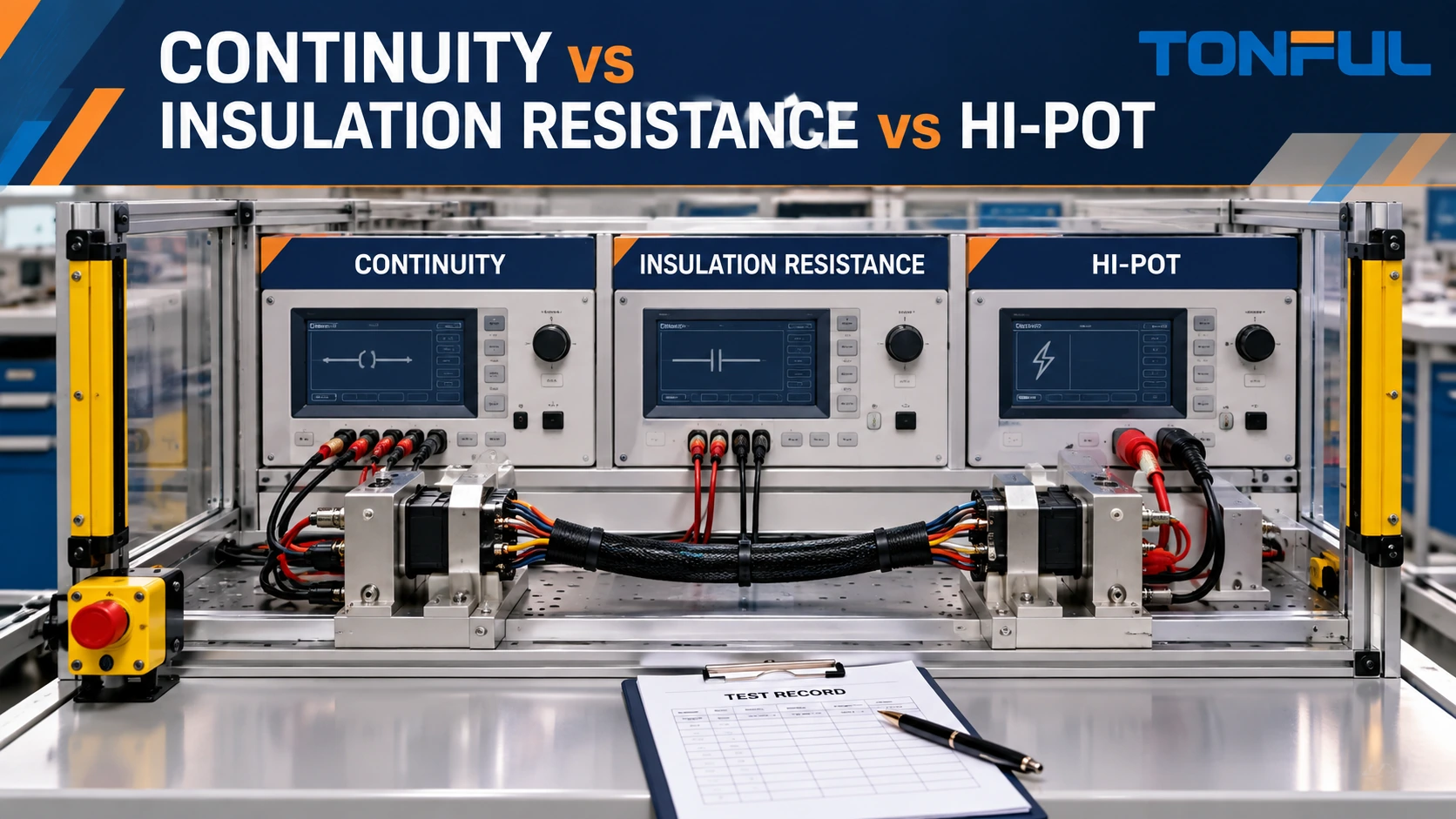
Continuity, insulation resistance and dielectric withstand (hi-pot) tests answer different questions. Continuity verifies intended conductive paths and can detect opens, miswires and shorts when the test matrix is complete. Insulation resistance applies a defined DC test condition and measures resistance between isolated conductors or between conductors and shield/chassis. Hi-pot applies a specified dielectric-withstand condition and monitors whether insulation breaks down or leakage exceeds the approved limit.
One test cannot be treated as a higher-resolution substitute for another. A cable can pass continuity while containing damaged insulation. It can show high insulation resistance at one condition yet fail a dielectric-withstand requirement. Conversely, applying an unnecessary high-voltage test can damage electronics, surge protection, filters or connectors. The product drawing, safety standard, customer specification or approved test plan must define which tests apply and their values.
On this page: Quick comparison | Safety | Continuity | Insulation resistance | Hi-pot | Planning | Record
Quick Comparison of the Three Tests
| Test | Primary purpose | Typical connection concept | Result type | Does not prove |
|---|---|---|---|---|
| Continuity/miswire | Verify intended paths, opens, shorts and wiring map | Low-energy measurement through selected conductors | Path resistance or pass/fail matrix | Insulation strength or signal performance |
| Insulation resistance | Measure leakage-related resistance across insulation | DC test between isolated groups | Resistance after defined time/condition | Dielectric withstand under a different stress |
| Hi-pot/dielectric withstand | Demonstrate insulation withstands specified test stress | AC or DC potential between defined conductive groups | Leakage/breakdown pass/fail | Correct pinout, data quality or long-term life |
These tests can be qualification, first-article, production or investigation controls. Their coverage need not be identical. For example, continuity/miswire may be applied to every assembly while a project uses qualification or sampled insulation evidence. Another product standard may require a production dielectric test. Do not infer frequency from the test name.
Workmanship requirements and electrical acceptance limits also serve different purposes. The IPC/WHMA-A-620 wire harness standard guide explains how an assembly standard can frame workmanship and inspection, but the released drawing, customer specification or approved test plan must still define the applicable electrical tests, limits and production coverage.
TONFUL’s wire harness continuity testing guide explains production matrix control in more detail. The current article focuses on selecting among three methods and preventing unsafe or technically invalid substitution.
Establish the Electrical Safety Boundary
All three tests require a defined device under test (DUT), but insulation resistance and hi-pot add stored-energy and high-voltage hazards. Only trained and authorized personnel should operate the equipment. Follow the tester manual, approved work instruction and applicable facility safety requirements.
Before connection, isolate the assembly from power and verify the de-energized condition using the approved method. Remove or isolate electronic modules, suppressors, lamps, sensors or other devices that the test condition could damage, but only when the controlled procedure permits it. Never use resistance or continuity mode on an energized circuit. Never apply a high-voltage source to an unidentified cavity.
Use guarded fixtures, interlocks, warning indicators, emergency controls and discharge provisions appropriate to the risk assessment. Keep exposed conductive parts inaccessible during the test. Treat the DUT as energized until the instrument has completed its discharge sequence and verification required by the procedure. Fluke’s official insulation-resistance testing application note emphasizes de-energizing, isolating equipment and discharging capacitance before and after testing.
Do not publish a universal “safe wait time.” Cable capacitance, test voltage, instrument discharge circuit, fixtures and connected components vary. Define a verified discharge/zero-energy method in the work instruction. Inspect leads, fixtures and barriers before use, and record equipment/calibration status.

Conceptual safety layout—not a facility procedure. Follow the approved tester manual, risk assessment and work instruction.
Continuity and Miswire Testing
Continuity testing confirms that intended endpoints are electrically connected. A complete test program also checks for opens, cross-connections, shorts between circuits and required shield or jumper paths. An audible multimeter beep may help troubleshooting, but it does not establish a controlled production matrix, measurement threshold or traceable result.
Define connector end views, cavity IDs and every legal path. Include intentionally unused cavities and no-connect requirements so a missing terminal is not confused with a reserved open circuit. For branched nets and splices, test every required destination. If components such as resistors, diodes or switches are included, define polarity, state and expected behavior.
Path resistance includes the wires, contacts, splices, adapters and fixture portions between the measurement points. Specify whether the result is simple continuity, two-wire resistance or a compensated/four-wire measurement. State test current, polarity where relevant, lead/fixture compensation, probe points, ambient condition and acceptance source. A low-energy production tester may not reproduce a loaded voltage-drop condition.
Continuity cannot validate data performance. High-speed assemblies may also require impedance, insertion loss, return loss, crosstalk or functional evidence. TONFUL’s data-cable eye-diagram guide explains why correct DC wiring is only the first layer of verification.
Insulation Resistance Testing
Insulation resistance testing applies a defined DC voltage between conductive groups and measures the resulting resistance, commonly after a specified stabilization or dwell condition. The result can be influenced by cable length/capacitance, temperature, humidity, surface contamination, connector geometry, test time and connected components.
Define which conductors are tied together, which remain isolated, and whether the return is another conductor group, shield, chassis or fixture. A scanner may connect many points, but its matrix must still match the drawing. Record ramp or charge behavior when relevant, dwell/reading time, instrument range and accuracy, current limit, environmental conditioning, discharge and acceptance document.
Electronic devices can distort the measurement or be damaged. Do not automatically apply an insulation test to a harness containing modules, filters, LEDs, surge suppressors or sensors. The design authority must define isolation or an alternative method. Fluke also notes the need to isolate electronic controls and considers temperature and capacitance in insulation testing.
Insulation resistance is not the same as conductor resistance. One describes the high-resistance path that should remain isolated; the other describes the intended low-resistance conductive path. Report them with units, connections and conditions so the records cannot be confused.

Conceptual insulation-resistance setup. Test voltage, grouping, time and limit must come from the approved requirement.
Dielectric Withstand or Hi-Pot Testing
Hi-pot testing intentionally stresses insulation at a specified AC or DC condition to detect breakdown, flashover, excessive leakage or workmanship defects defined by the acceptance plan. Associated Research describes dielectric withstand testing as applying high potential beyond normal operation to evaluate insulation withstand. That general purpose does not supply the correct voltage, waveform, ramp, dwell or leakage limit for a particular cable assembly.
The plan must define AC or DC, test voltage, ramp, dwell, current/leakage limit, conductor grouping, return point, arc detection if used, discharge, fixture and environmental conditioning. AC and DC results are not interchangeable without the governing requirement. Cable capacitance can affect current, especially with longer assemblies, so instrument capacity and nuisance-trip behavior require review.
Do not repeat a hi-pot test casually after a failure or on returned product. Repeated dielectric stress can be restricted by the product specification. Preserve the failed sample, tester record and failure location; investigate fixture flashover, contamination, connector spacing, damaged insulation and incorrect program before authorizing retest. A “pass after retest” does not erase the first event.
Hi-pot does not prove correct wiring or normal-load performance. Run continuity/miswire checks at the defined point in the sequence. Where the assembly includes electronics, identify whether testing occurs before module connection or uses another approved boundary. The TONFUL overmolded cable assembly guide shows why finished geometry and interfaces also need mechanical verification.

Conceptual hi-pot matrix—not a voltage or leakage recommendation. Use only the approved product-specific test program.
Build a Controlled Test Sequence
Sequence tests to protect personnel, equipment and evidence. A common planning logic is identification and visual inspection, continuity/miswire, required low-resistance checks, insulation resistance where specified, dielectric withstand where specified, discharge verification and final continuity/functional confirmation. This is not a universal mandatory order; the approved plan may differ because of components, conditioning or regulatory requirements.
Allocate samples deliberately. State whether the same samples receive environmental conditioning and all electrical tests, whether independent groups are used, and whether an unaged baseline is retained. Define sample quantity, selection rationale, destructive-test allocation, invalid-test criteria, replacement-sample rules and approval authority.
After environmental exposure, compare initial and aged values only when the requirement calls for it. Preserve raw readings, not just pass/fail. For marine or wet applications, assembly-level sealing and electrical re-test may be required by the qualification plan; TONFUL’s marine harness guide provides application context without assigning universal test severity.
Test-program control is essential. Record software/program revision, fixture ID, scanner mapping, instrument model/range/accuracy, calibration status, operator authorization and DUT revision. Challenge fixtures/programs with known conditions at the defined interval, and establish reaction rules for failures or equipment alarms.
Copyable Cable Assembly Test Record
| Record field | Required entry |
|---|---|
| DUT identity | Part number, revision, lot and sample/serial ID |
| Test stage | Qualification, first article, production or investigation |
| Acceptance source | Drawing/specification/standard and revision/section |
| Test type | Continuity/miswire, resistance, IR or hi-pot |
| Connection matrix | Source/return points, tied groups, shield/chassis |
| Instrument | Model, range, accuracy and calibration status |
| Fixture/program | IDs and revisions; compensation method |
| Parameters | Current or voltage, AC/DC, ramp, dwell and limit as applicable |
| Environment | Temperature, humidity and conditioning |
| Initial/aged result | Raw value and change where required |
| Discharge/zero-energy | Method and verification result |
| Failure | First event, location, mode and preserved evidence |
| Invalid/retest disposition | Reason, authorization and sample rule |
| Decision | Pass/fail, reviewer and date |
Define Cable Assembly Testing With TONFUL
Send TONFUL the released drawing and pinout, device boundaries, required test methods, acceptance sources, sample plan, production coverage and safety constraints. TONFUL can review continuity matrices, fixture/testability needs and evidence records against the defined assembly. Insulation-resistance and hi-pot conditions must remain tied to approved product-specific requirements and safe equipment procedures.