
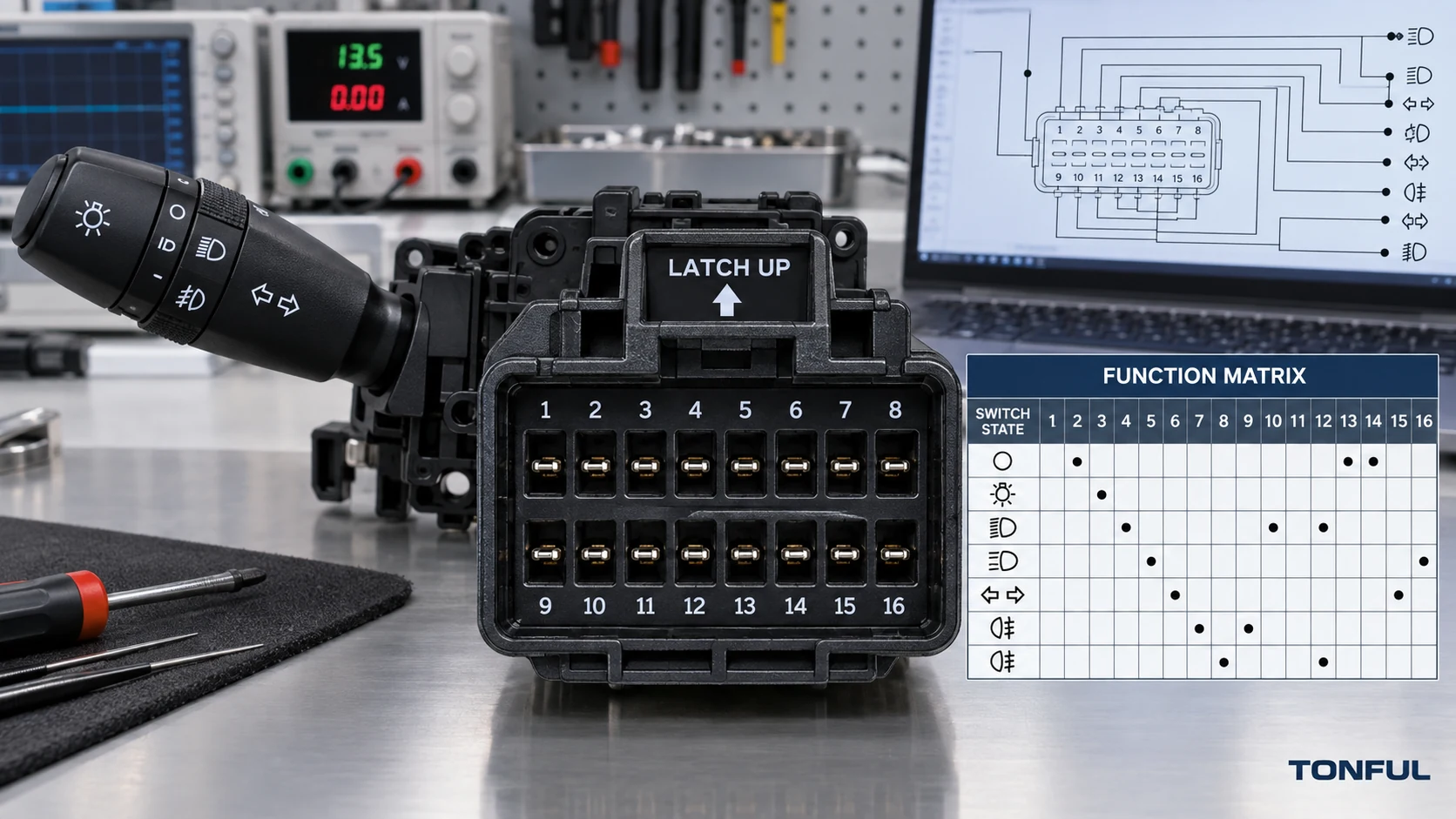
A combination switch pinout is meaningful only when its connector view, cavity numbering and switch states are defined. A diagram viewed from the harness side can appear mirrored when compared with the switch-side face. The same connector shell may also contain different populated cavities, terminal sizes, contact paths, resistor values or network circuits. Guessing from wire color or physical fit can damage a module, energize the wrong load or create an intermittent fault.
This guide shows how to orient the connector, identify cavities, distinguish terminals from circuits, build a switch-state truth table and decide whether the device uses direct contacts, coded values or network commands. Product drawings, vehicle service information and approved samples remain the acceptance sources; there is no universal combination-switch pinout.
On this page: Orient the Connector | Classify Pins and Circuits | Build a Truth Table | Verify Safely
Orient the Connector Before Numbering Cavities
Eight Rules That Prevent Mirrored Pinouts
| No. | Rule | Required evidence | Error prevented |
|---|---|---|---|
| 1 | State the viewing side | Switch face, harness face, rear wire-entry side or drawing datum | Left-right mirroring |
| 2 | Fix one orientation reference | Latch up, keyway up, cavity-one mark or controlled datum | Rotated numbering |
| 3 | Record connector identity | Shell family, keying, color, latch and mating connector | Wrong connector variant |
| 4 | Number every cavity | Include empty, sealed and unused positions | Shifted pin count |
| 5 | Separate cavity from terminal | Cavity number, terminal size and populated status are different fields | Assuming an empty cavity carries a circuit |
| 6 | Separate terminal from wire color | Use circuit function and diagram reference, not color alone | Harness-revision mistakes |
| 7 | Record every switch state | Neutral, detents, momentary actions and rotary rings | Incomplete truth table |
| 8 | Identify architecture | Direct contact, relay request, coded value or network command | Unsafe or meaningless testing |
An Unknown result is not a pass. Keep the pinout unreleased when the viewing side, cavity-one reference, architecture or evidence source is unresolved.
Use Connector-End Photographs Correctly
Record make, model, production range, market, LHD/RHD and stalk position because pinouts can change within one model family. Describe photographs as switch-side mating face, harness-side mating face or wire-entry side. Add latch up or another physical datum. Never mirror a photograph for visual convenience.
Capture every character of the OE service number and identify its source. Separate OE service, superseded OE, supplier, engineering, housing/casting, and customer stock numbers. A molded number on the plastic housing may identify a shared subcomponent rather than the complete switch. The OE-number verification guide explains how to record supersession direction and validation status.
For U.S.-market vehicles, NHTSA vPIC can support manufacturer-reported vehicle identification data. It does not confirm combination switch interchangeability, OE supersession, connector pinout, electrical architecture, or product acceptance.
Vehicle-manufacturer information remains the controlling source for application-specific electrical details. Scania’s official repair-information overview states that the chassis number is the key to retrieving a vehicle specification and that wiring diagrams are used to find electrical faults. That supports a disciplined sequence: identify the exact chassis first, then consult the applicable diagram rather than assuming that two trucks sharing a model badge use the same stalk. See the Scania repair and maintenance information package. Access conditions and document coverage may vary by market.
Create a Connector Layout Record
The layout record should identify rows and columns exactly as the controlled drawing does. If no numbering is molded into the shell, establish a temporary inspection grid tied to the latch and mark it as an inspection convention rather than an OE designation.
| Layout field | Required entry |
|---|---|
| Viewing direction | Switch mating face, harness mating face or wire-entry side |
| Orientation datum | Latch/keyway direction and cavity-one reference |
| Connector identity | Shell, keying, color, latch and mating part where known |
| Cavity pattern | Row/column arrangement and total cavity count |
| Population | Terminal present, empty, sealed or intentionally unused |
| Terminal detail | Size, type, plating or other controlled identifier where required |
| Evidence | Drawing number/revision, service information, photograph and reviewer/date |

A straight-on connector end view must show the viewing side, latch orientation and cavity numbering reference.
Compare Connector Shell and Populated Cavities
Photograph both connector faces straight-on with the latch, keyway, or cavity-one reference visible. Compare shell family, keying ribs, polarization, latch, cavity count, populated terminals, terminal size, seal interface, and signs of bent or backed-out terminals. Never mirror one photo to make it resemble the other.
A physically mating connector is not proof of electrical fit. Record empty cavities as well as populated ones because a missing illumination, horn, cruise, communication, or direct-load terminal can distinguish configurations within the same shell family.
Classify Pins, Circuits and Switch Architecture
Identify the Control Architecture Before Energizing
Determine whether the switch directly reverses lighting or wiper load path, switches a relay, sends a low-current request to a BCM or steering-column or body-control module, produces resistance-coded states, or communicates over LIN/CAN or another specified interface. A multifunction stalk assembly may combine more than one method. Terminal size and button count cannot establish the architecture.
Direct-load contacts require verification of the actual current path, terminal allocation, loaded voltage drop or contact resistance, and thermal behavior under product-specific conditions. Low-current request switches require the correct reference voltage, ground, logic state, or resistance range. Networked units add hardware, software, coding, wake/sleep behavior, diagnostics, and initialization dependencies.
The automotive combination switch contact-resistance testing guide explains how test points, load conditions, contact paths, and acceptance sources must be defined before comparing results.
Safety Boundary for Steering-Column Testing
Safety boundary: Follow the vehicle-specific service procedure before disconnecting or probing steering-column circuits. Disable the SRS only as directed by the vehicle manufacturer, including the specified isolation, waiting and restoration steps. Do not substitute a universal waiting time because procedures differ by vehicle and system.
Never apply external power or ground to an unidentified cavity, use resistance or continuity mode on a powered circuit, or probe an SRS circuit. Do not use a conventional test light on BCM, LIN, CAN or another low-current electronic interface. Honda warns that tampering with, disconnecting or using electrical test equipment on SRS wiring can make the system inoperative or cause accidental inflator firing; follow the applicable service manual rather than a generic pinout. See the Honda SRS safety warning. A vehicle-manufacturer technical procedure published through NHTSA likewise states not to measure resistance of airbag components because accidental activation can result; its instructions apply only within the identified repair scope. See the NHTSA-hosted manufacturer SRS procedure.
Bench power may be applied only after power, ground, permitted voltage range, polarity, current demand and current limit have been confirmed from controlled documentation. Use a protected breakout harness, fused or current-limited supply and appropriately rated high-impedance instrument for the identified circuit. Use terminal-compatible probes so a coarse meter tip does not spread a female terminal, damage plating or puncture a seal. If the circuit boundary, SRS relationship or module interface remains uncertain, stop testing and obtain the vehicle-specific procedure.
Build the Pinout and Switch-State Truth Table
Do not use a generic internet pinout. Number cavities from the controlled connector drawing and state the viewing direction. Complete one row for every cavity, including blanks.
| Cavity | Removed-part terminal/function | Candidate terminal/function | OFF state | Turn/beam state | Wiper/washer state | Cruise/secondary state | Evidence source | Result |
|---|---|---|---|---|---|---|---|---|
| Enter cavity | Power, ground, lamp, relay, pump, illumination, signal, network, or empty | Enter candidate function | Open/closed/value | Path/value | Path/value | Path/value | Diagram and test | Pass/Fail |
| Enter cavity | Enter function | Enter candidate function | Enter | Enter | Enter | Enter | Enter source | Pass/Fail |
| Enter cavity | Enter function | Enter candidate function | Enter | Enter | Enter | Enter | Enter source | Pass/Fail |
For direct-contact switches, record which terminals connect in neutral and in every turn, beam, flash, horn, wiper, washer, or cruise position. For resistance-coded switches, record each commanded resistance window, tolerance, test points, instrument method, and module recognition. For relay or BCM requests, record the expected voltage or ground logic and the receiving input. For networked products, record interface, message or state evidence, software revision, coding, and DTC behavior without inventing universal values.
Understand NO, NC, Common and Coded Outputs
For a passive contact, common is the terminal shared by two or more commanded paths; it is not automatically battery positive or ground. Normally open and normally closed describe the contact state at a defined rest position. These terms must be tied to the exact mechanism and test points. A momentary flash or washer contact may close only while held, while a turn-signal path can latch mechanically until self-cancel.
Resistance-coded and voltage-coded switches do not produce a simple open/closed answer. Record the specified terminal pair, supply or reference conditions, instrument method, value window and tolerance for every state. A LIN or CAN device requires network and software evidence; continuity probing cannot reveal its complete command mapping.
Separate Pinout From Wire Color and Harness Routing
Wire colors can change with market, harness supplier or production revision. Use the circuit identifier and cavity number as the primary references, then record wire color as supporting evidence. A splice, relay or controller between the stalk and load means the terminal name should describe the immediate circuit role, not assume that it directly powers the final device.
Verify Illumination, Function Authority, and Vehicle Architecture
Identify power, ground, illumination supply, illumination return, dimming or PWM input, and polarity. A stalk can perform one primary function while illumination, horn, cruise, menu, or another channel remains incorrect. Check symbol orientation, color, brightness method, and light leakage only against the approved appearance requirement.
Trace each command from the stalk to its receiving device. A direct circuit may carry lamp, washer-pump, or relay-coil current; a coded circuit may present resistance or voltage states; a networked assembly may send a module request. Confirm the receiving ECU, wake state, coding, and fallback behavior from the controlled vehicle diagram.
The heavy-duty combination switch failure guide helps separate stalk faults from wiring, relay, controller, connector, and installation problems.
Verify the Pinout and Release the Record
Test Every Mechanical and Electrical State
Verify turn-signal direction, high/low beam, flash-to-pass, horn, front and rear wiper stages, intermittent adjustment, washer commands, cruise-control functions, menu controls, illumination, and every secondary detent included in the approved configuration. Identify whether each state is a mechanical contact path, direct load, relay request, resistance-coded value, voltage state, or network message.
A correct connector fit does not establish electrical compatibility. The approved sample must reproduce the specified command matrix and interact correctly with the truck’s relays, body controller, instrument cluster, steering-column module, and other receiving devices. Mechanical self-cancel geometry must also match the steering-column interface.
If replacement affects coding, calibration, steering-angle information, cruise authorization, or diagnostic status, follow the vehicle-specific service procedure. Record software or parameter versions, DTC state, initialization result, and every restored function; never borrow a procedure from a visually similar truck.
Use a Copyable Pinout Verification Record
| Check field | Controlled reference | Measured sample | Evidence source | Result |
|---|---|---|---|---|
| Connector viewing side and datum | Enter | Enter | End-view photo/drawing | Result |
| Cavity numbering and population | Enter | Enter | Cavity map | Result |
| Terminal size/type | Enter | Enter | Drawing/inspection | Result |
| Architecture | Enter | Enter | Diagram/test | Result |
| Neutral/OFF state | Enter | Enter | Truth table | Result |
| Turn/beam/flash/horn states | Enter | Enter | Truth table | Result |
| Wiper/washer states | Enter | Enter | Truth table | Result |
| Cruise/menu/secondary states | Enter | Enter | Truth table | Result |
| Illumination and dimming | Enter | Enter | Diagram/test | Result |
| Coded/network behavior | Enter | Enter | Approved method | Result |
| Final disposition | Reference revision | Sample ID/lot | Approval record | Approved/Conditional/Rejected |
Confirm the Bench Result in the Intended Vehicle
Use an identified production-intent sample and truck. Verify seating, retention, connector latch, harness clearance, stalk reach, symbol orientation, every detent, self-cancel, illumination, diagnostics, and operation under the specified electrical architecture. Distinguish switch faults from wiring, relay, fuse, controller, actuator, coding, or installation faults before rejecting the sample.

Bench evidence should reproduce every specified stalk state before the pinout is confirmed in the intended vehicle.
Apply Evidence-Control Rules Once
Maintain one evidence index containing vehicle source, document revision, OE chain, sample and lot, photograph orientation, dimensions, cavity map, pinout, architecture, function results, test equipment, conditions, acceptance source, approver, and date. If sources conflict, retain them, mark the decision unresolved, and obtain clarification from the controlling vehicle, customer, engineering, or supplier source. Do not choose the more convenient record.
Sample approval applies only to the named configuration. Control changes to housing, resin, contacts, plating, springs, resistor values, PCB, software, illumination, connector, tooling, site, sub-supplier, test method, packaging, and labels. Use the combination switch RFQ and Sample Approval Checklist to define quotation and release evidence before expanding fitment claims.
Work With TONFUL
TONFUL’s automotive combination switch range presents current vehicle applications and OE reference numbers. Send the exact vehicle and market, production range, stalk position, LHD/RHD, complete OE reference, removed-part photos, dimensions, connector-end view, cavity map, pinout, architecture, function matrix, sample quantity, and validation requirements. Final fitment remains tied to controlled evidence and an approved application sample.
