
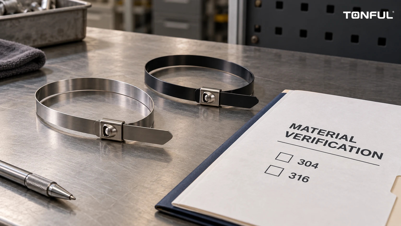
A stainless steel cable tie is not defined by “metal” alone. Alloy, band edges, coating, locking head, tool and contact surface influence retention and insulation damage. A 316 band with the wrong lock or a poorly cut tail may be worse than a correctly specified 304 tie in a less demanding location.
This guide combines the decisions for solar, marine, industrial and vehicle applications: alloy, coating, ball-lock design and approval evidence. It asserts no universal working load, salt-spray lifetime or TONFUL temperature rating.
Start With the Actual Service Conditions
Define whether the tie bundles cable, fixes conduit, positions a hose or provides code-relevant support. Identify bundle diameter and compressibility, harness mass, spacing, bend radius, vibration, access and maintenance. Include adjacent metals, jacket material and sharp edges.
Map exposure rather than writing only “outdoor.” A coastal rack combines chloride, moisture and heat. A process line may have chemical washdown; a vehicle underside may see road salt, grit and flex. These combinations affect steel and coating. Record hot surfaces and cable movement.
The UL cable-tie application guidance distinguishes a device used to secure wiring from one evaluated for support under specified installation conditions. An exact listing, Type designation, package marking and associated fixing device matter. A metal tie’s material label alone does not show that it is approved for primary support or for every exposure. Use the applicable installation rules and customer specification for the actual project.
Compare 304 and 316 Without Overpromising
Both are austenitic stainless steels, but 316’s molybdenum content generally improves resistance to localized chloride attack relative to 304 under many conditions. That does not make 316 immune to pitting, crevice corrosion or attack from every chemical. The Outokumpu corrosion overview explains that sufficiently high chloride exposure can still cause localized corrosion in stainless steel. Temperature, deposits, wet/dry cycles and sheltered crevices change the result.
| Decision area | 304 stainless | 316 stainless | Evidence to request |
|---|---|---|---|
| Mild indoor or sheltered service | Often a candidate | May be unnecessary unless specified | Service environment and controlled material grade |
| Coastal or chloride exposure | Requires project-specific review | Often preferred starting candidate | Exposure profile, corrosion plan and finished-tie evidence |
| Aggressive cleaning chemicals | Cannot be approved by grade name alone | Also not universally resistant | Chemical, concentration, temperature and contact time |
| Dissimilar-metal contact | Galvanic system must be evaluated | Galvanic system still must be evaluated | Adjacent metal, electrical contact and drainage |
| Purchase and traceability | Verify heat/lot and grade | Verify heat/lot and grade | Material certificate, product ID and supplier change control |
The TONFUL 304 vs 316 selection guide provides a deeper alloy-only comparison. In a purchase decision, also check band thickness, width, finished edge, head design, coating and installation tool. Changing alloy while keeping an unsuitable edge or mounting interface can leave the original failure mechanism untouched.
Ask for a material certificate tied to the delivered lot where grade confirmation matters. A catalog adjective such as “marine grade” is not a substitute for the controlled alloy designation and product-specific corrosion evidence. If a coated band hides the metal, traceability is especially important. Do not describe an unknown dark or silver tie as 304 or 316 from color.
Coated Versus Uncoated Bands
A coated tie can provide a barrier between the steel and cable jacket and may reduce abrasion or cutting risk during tightening. It may also change grip, band thickness, head engagement, installation temperature and the cable bundle’s long-term pressure. Coating chemistry and thickness are not interchangeable. A colored or black appearance does not by itself prove a specific polymer, UV resistance, electrical insulation or chemical compatibility.
An uncoated band may be appropriate when direct metal contact is allowed and the design values a simpler surface or higher temperature capability. But it needs careful attention to deburred edges, the tail, bend radii and a protective interface around delicate cable jackets. A bare tie should not be dragged over insulation while tensioning. If the tied object expands, creeps or vibrates, test whether pressure and fretting are acceptable over service life.
The BAND-IT Ball-Lok product information describes coated and uncoated versions and says its coating can reduce cable-insulation abrasion risk. That is evidence about the named manufacturer’s products, not proof of TONFUL coating material or performance. Specify the exact TONFUL candidate’s coating type, thickness, coverage, adhesion, temperature range and compatibility with the contacted cable.
| Condition | Coated option to verify | Uncoated option to verify |
|---|---|---|
| Sensitive jacket or hose | Coating integrity at edges, buckle and cutoff | Protective sleeve, edge finish and applied tension |
| Heat | Coating’s own operating limit and aging | Steel, lock and cable limits still govern |
| Chemicals | Coating swelling, cracking or delamination | Alloy and crevice behavior under deposits |
| Electrical proximity | Insulation claim only with specific evidence | Exposed conductive band and clearances |
| Inspection | Hidden metal corrosion and coating damage | Visible metal condition, sharp tail and wear |

Conceptual cable-contact comparison only; coating chemistry, thickness and permissible tension require product-specific evidence.
Do not assume a coating makes the entire assembly electrically insulating. The buckle, tail or cut edge may expose metal, while abrasion and aging can damage the layer. If electrical isolation is a functional requirement, use a separately defined insulation system and test its continuity and durability on the finished assembly. Similarly, a coating does not fix a crevice that traps salt water beneath a band.
Understand Ball-Lock and Other Closure Designs
Ball-lock describes a self-locking head in which a ball or similar element grips the inserted metal band. It can support efficient installation, but the actual lock strength depends on band geometry, head construction, insertion direction, tool setting and the tested bundle. Other designs use buckles, tabs, crimping or a separate locking clip. Their listed strengths cannot be compared without the same test method and failure definition.
Check minimum and maximum bundle diameters, band length and width, head size, clearance to adjacent parts, tail cutoff and whether re-tensioning is permitted. A tie may appear closed while the band is not fully engaged. The product drawing should define a visual or functional inspection point. For a concealed installation, determine how the assembler confirms engagement before the harness is covered.
Tool compatibility matters. A dedicated metal-tie tool can set repeatable tension and cut cleanly; a general-purpose cutter may leave a sharp projection. The manufacturer guidance for the exact band and tool should govern setup. Record tool model, setting, calibration status, operator instruction and cutoff-blade changes. Do not transfer another brand’s settings to a TONFUL tie without validation. The cable tie tensile-strength guide explains why rated loop strength is not installed working load.
The TONFUL general stainless steel tie guide explains basic constructions. This article’s purchasing decision goes further: choose alloy, interface and lock together, then validate their combined installed behavior. A nominally higher loop tensile result cannot compensate for an exposed sharp edge or unstable support fixing.
Installation Sequence and Checks
First confirm the selected band, coating and tool against the work instruction. Inspect the tie for damage, twisted band, chipped coating or an abnormal locking head. Place it around the intended bundle without trapping a connector latch, small signal wire or service loop. Route the band so the lock does not rest on an edge or on the cable’s highest-stress point.
Tension in the specified direction, with the cable bundle and any protective sleeve in the production configuration. Cut the tail using the validated tool and check the residual edge by the approved inspection method. Never rely on a gloved finger alone as a quantitative sharp-edge test. Confirm the cable is retained but not crushed, the bend radius and connector slack remain, and the band cannot migrate into a hot or moving component.
Where a metal band touches aluminum or painted steel, inspect the joint system, not merely the tie. Surface damage may expose base metal; trapped moisture may create a crevice. Define drainage, protective layers and inspection access. If the mounting point changes, reassess whether the tie is acting as a bundle restraint or a structural support. A tie around an unsupported cable cannot automatically take the place of an approved bracket or fixing device.
For rework, cut and remove the tie without nicking insulation. Do not reuse a single-use lock unless the manufacturer explicitly permits it and a validation procedure exists. Inspect the old band and jacket for the original cause of removal; replace a failed tie with the same design only after confirming it was not the wrong alloy, coating, tool setting or route.
Qualify the Finished Tie and Installed Assembly
Request separate evidence for material identity, loop or locking performance, coating condition and the installed assembly. The applicable test method and acceptance limits should come from the product specification, customer drawing, electrical installation requirement or approved qualification plan. Avoid publishing a single “working load” derived by dividing a catalog tensile value by an arbitrary factor.
Use production-intent samples from known lots. Define sample count and allocation, unaged controls, sequential versus independent exposures, destructive tests, replacement rules and the reviewer. Condition specimens under the agreed heat, cold, moisture, chloride or chemical exposure; then inspect cracks, coating loss, corrosion, lock movement, retention and cable damage. Test the actual bundle or representative mandrel and installation tool where relevant.
| Record field | Required entry |
|---|---|
| Product identity | TONFUL part, drawing revision, alloy, coating and lot |
| Installation | Bundle, substrate, tool, setting, tail orientation and operator |
| Baseline | Lock/loop result, contact condition and cable inspection |
| Conditioning | Method, duration, temperature, solution and sequence |
| Retest | Retention, slip, coating change, corrosion and cable condition |
| Failure | First failing interface, photographs and retained sample |
| Decision | Acceptance-source document, deviation, approver and date |

Inspect lock engagement, band finish and the cable interface together after the specified installation and conditioning steps.
For primary electrical cable support, confirm certified scope and compatible fixing device rather than inferring capability from alloy or strength. UL emphasizes ratings and markings; the project’s authority and code determine use. Do not claim TONFUL certification without a current listing and applicable markings. The TONFUL solar cable-tie comparison addresses alternatives where a metal tie is not automatically the best choice.
Failure Evidence and Corrective Action
If a stainless tie loosens, preserve the lock and tail before removal. Check whether the head slipped, band was under-tensioned, bundle relaxed, tool drifted or the tie was installed backward. If insulation is damaged, look for a sharp cut end, uncoated edge, over-tension, vibration and movement. If corrosion appears, map deposits and wet areas rather than calling every brown stain a base-metal failure; distinguish surface contamination from pitting and crevice attack with appropriate examination.
Compare failed parts to retained samples and lots. Record exposure duration, alloy certificate, coating batch, installation tool and changes in adjacent material or cleaning practice. A corrective action may require a new alloy, coated interface, different lock, protective sleeve, revised cutoff method or improved drainage. Validate the changed assembly and update the drawing, work instruction and inspection plan before broad release.
Request a TONFUL Proposal
TONFUL’s cable tie range can be screened against your drawing and service environment. Send the bundle diameter and jacket, mounting layout, temperature and chemical exposures, chloride conditions, vibration, intended support function, required alloy and coating evidence, installation tool preference and acceptance plan. Request samples and the controlled product specification for the proposed model.
The release decision should identify the precise band, head, coating, tool, substrate and approved application. A switch from 304 to 316, bare to coated, or one ball-lock design to another is a design change to validate, not just a purchasing substitution.
