
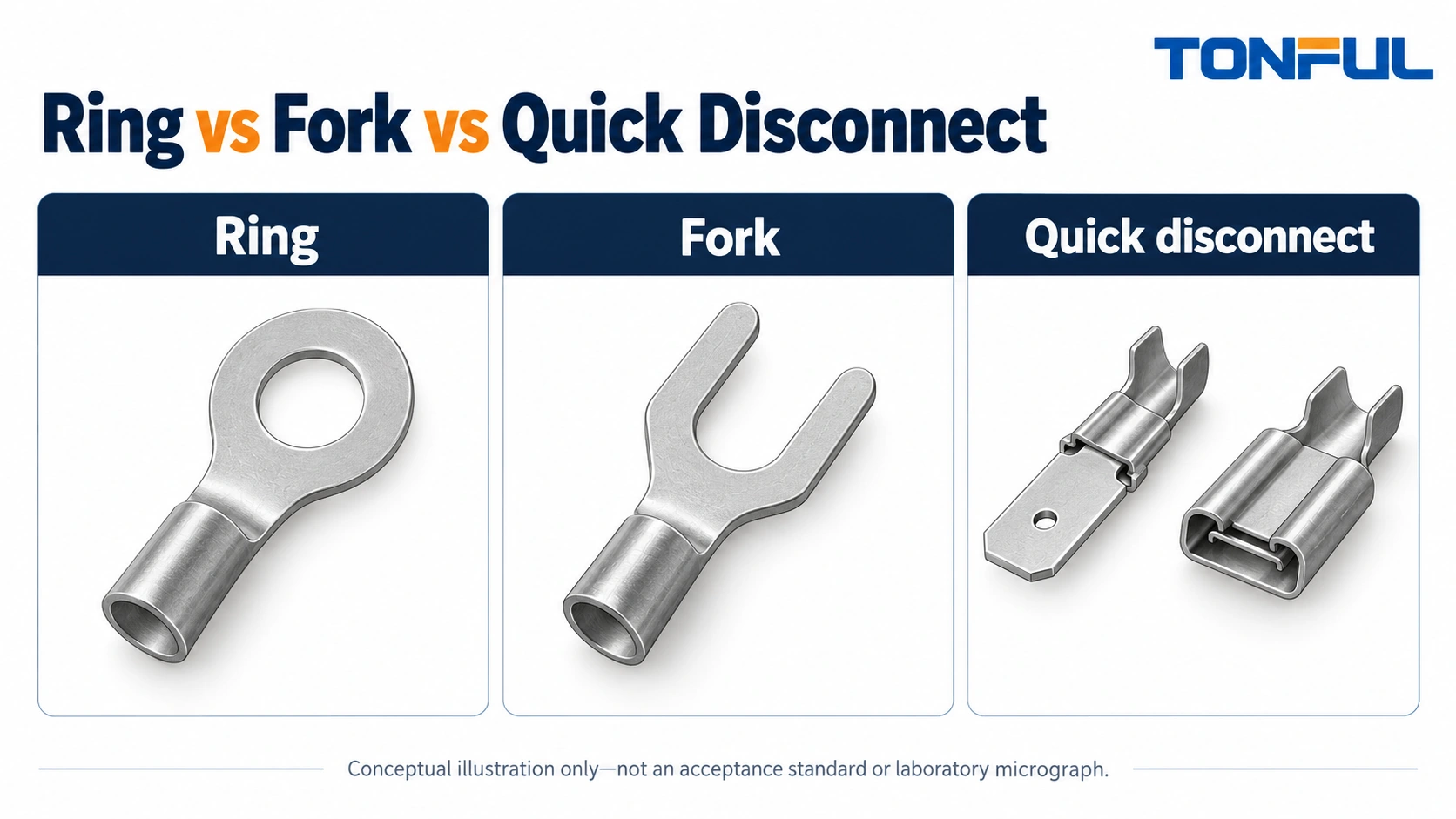
The decisive question in ring vs fork vs quick disconnect terminals is what connection point the equipment provides. A ring terminal has a closed eye for a suitable stud or screw attachment. A fork terminal has an open-ended slot for an approved fastening arrangement. A quick-disconnect terminal uses a matched blade and receptacle interface rather than a stud connection.
These are not three interchangeable shapes for the same job. Start with the equipment drawing and service task, then compare conductor range, installed space, insulation, tooling and inspection. The right choice is the documented combination that fits both the electrical attachment and the way the assembly will be installed and maintained.
Jump to: Interface map · Ring · Fork · Quick disconnect · Production · Record
Ring vs Fork vs Quick Disconnect Terminals: The Interface Map
Define the attachment and removal action
A closed ring eye generally requires access to place it over the stud or screw. An open fork slot can permit insertion beneath approved loosened hardware without fully removing that hardware. A quick-disconnect receptacle mates with a specified blade and is removed according to its design, including any locking feature.
The practical comparison is therefore about attachment, access and controlled service, not a universal ranking of strength. A ring can remain geometrically captured around a stud while a loose fastening connection is still electrically unacceptable. A fork can be convenient but inappropriate if the equipment does not allow an open-slot terminal.
| Decision | Ring terminal | Fork terminal | Quick disconnect |
|---|---|---|---|
| Equipment interface | Suitable stud or screw with closed-eye attachment | Approved screw or stud arrangement for open slot | Matched blade and receptacle |
| Key dimensions | Hole, tongue width/thickness, wire range | Slot, tongue width/thickness, wire range | Tab width/thickness, mating features, wire range |
| Assembly access | Place eye over attachment point | Slide slot under permitted hardware | Insert along required mating direction |
| Service action | Remove or release specified hardware | Loosen hardware as permitted | Release lock if present and separate interface |
| Main limitation | Needs suitable hardware and access | Open-slot use must be approved | Same nominal blade width does not prove compatibility |
Avoid the ambiguous word spade
Some catalogs use spade for a fork tongue; others use it for a flat blade quick-disconnect interface. A purchase order reading “blue spade terminal” can therefore describe different products. Use a drawing, exact part number and interface description rather than relying on that term.
TONFUL’s wire-terminal sourcing information is a useful place to begin a shape-and-interface inquiry. Include an image only as supporting context. The controlled dimensions and application information must carry the specification.
Choose a Ring Terminal for an Approved Closed-Eye Attachment
Check the complete hardware interface
Select the ring opening for the designated stud or screw, then check tongue width, thickness and available seating area. A ring that passes over the thread can still interfere with a terminal recess or adjacent barrier. Confirm the required washer and nut arrangement, thread engagement and any anti-rotation provisions.
Use the equipment’s tightening instructions where torque applies. Do not select torque from insulation color, conductor area or a generic ring-terminal chart. The fastening hardware and equipment construction define the applicable requirement.
Do not drill or file the ring opening to make an undersized eye fit. That changes the supplied part and can affect plating and surrounding material. Request another controlled part or an approved design change rather than treating modified geometry as an equivalent terminal.
Plan installation and replacement access
Ring terminals can suit attachments where a closed eye is required, but the assembly sequence must allow the eye to be installed. Check whether the stud hardware is captive or removable, and whether replacement would disturb other circuits sharing the location.
Do not assume stacked rings are allowed without checking the equipment instructions. Available thread, seating surfaces, permitted terminal quantity and wire routing matter. A crowded stack can create access and strain problems even if each ring individually matches the stud.
Where an exposed terminal is appropriate within a protected design, compare specific non-insulated terminal forms. Their geometry and insulation strategy remain separate decisions. A bare ring does not provide the same protection as an insulated or enclosed connection.
Choose a Fork Terminal Only When the Fastening Arrangement Permits It
Confirm that the open slot is acceptable
A fork’s open slot changes how the terminal can enter and leave the fastening point. That can be useful where service access favors sliding the terminal beneath approved hardware, but convenience does not override the equipment’s permitted terminal form.
Compare slot width, slot depth, tongue width and tongue thickness against the actual attachment. Check that the bearing hardware engages the intended area. Do not assume a fork intended for one screw arrangement is acceptable on another simply because its slot clears the thread.
Fork designs also vary. Standard, flanged and other retention-oriented forms can have different geometry and instructions. Do not claim that a fork is locking or equivalent to a ring unless the selected product documentation supports that statement for the application.
Make loosening a controlled service operation
Service access is a legitimate selection factor, but the connection must still be isolated and restored under an approved procedure. Define which hardware is loosened, how the terminal is reseated and how tightening is verified. An open slot is not permission to pull a terminal out of an energized connection.
For US workplace electrical tasks, OSHA 1910.333 addresses deenergization and related work practices. Qualified personnel must follow the applicable site and equipment instructions. This comparison does not authorize live work or generic substitutions in safety-related circuits.

Choose a Quick Disconnect for a Matched Tab and Receptacle
Specify both blade dimensions and mating features
A quick disconnect is selected around its mating interface. Record tab width and thickness, receptacle family, orientation, retention arrangement and any housing requirements. Two receptacles with the same nominal width can have different thickness compatibility or locking details.
Distinguish straight, flag and other wire-exit arrangements. They can affect overall height, wire bending space and mating access. A flag design that fits a shallow enclosure may require side clearance that the straight version did not need.
Also distinguish male tabs, female receptacles and combined forms. A request for a quick-disconnect terminal is incomplete if the supplier does not know which half is required. If both halves are purchased, identify them as a controlled pair rather than assuming that two same-size catalog items match.
Protect the contact interface during service
Mate and remove the interface according to its instructions. Release a latch where required, use any specified extraction method and avoid pulling on the wire as an improvised removal technique. A damaged receptacle should not be tightened with pliers and returned to service without an approved disposition.
Do not assume a quick-disconnect interface may interrupt load current or withstand unlimited mating cycles. Those capabilities require specific product and application evidence. A disconnect that is convenient for module service can still require isolation before separation.
A ferrule from the cord end terminal family is not a substitute for a male quick-disconnect blade. Ferrules prepare stranded wire for compatible terminal entries; their sleeve geometry and function are different. This distinction is especially important when catalog descriptions use the broad word pin.
Compare Production, Protection and Service Tradeoffs
Keep conductor termination separate from interface selection
All three forms may be available with different conductor barrels and insulation arrangements. Compare wire range, strand compatibility, insulation diameter and tooling for the selected part. The presence of a ring, fork or receptacle does not determine the crimp profile by itself.
A conventional single-wire terminal generally has one conductor termination, but the exact construction can add insulation support or other application steps. Count actual crimp locations and tool operations from the selected instructions. Do not reduce an open-barrel conductor-and-support process to an assumed one-squeeze operation.
Ask TONFUL’s crimping-tool team to identify compatible tooling for the exact wire and terminal. A general die range does not establish that every part in that range is correctly formed. Include the available production method when requesting the recommendation.
Compare total installed length and protection
Count the terminal body, wire exit, protective sleeve, mating overlap or hardware stack and service clearance. A compact loose terminal may become the largest installed option after insulation and access requirements are added. Compare layouts in their completed condition, not just parts laid on a bench.
Insulation does not automatically mean sealing. TONFUL’s nylon-insulated terminal range can support an insulated-parts inquiry, but each selected part needs its own application basis. Moisture protection, touch protection and enclosure spacing are different requirements.
Inventory complexity also differs. A ring assortment may need several stud sizes for one wire range; a quick-disconnect system may need separate mating parts, orientations and housings. Keep look-alike parts separated and label by controlled identity, not sleeve color alone.
| Review area | Information to compare across the three options |
|---|---|
| Conductor end | Wire construction, range, insulation fit and barrel design |
| Assembly route | Crimp locations, cavity needs, hardware or mating steps |
| Installed envelope | Length, orientation, protection and wire bending space |
| Inspection | Crimp condition plus fastening or full mating verification |
| Repair | Hardware access, extraction method and replacement parts |
| Evidence | Part drawings, application instructions and required qualification |
Release the Choice With an Interface Verification Record
Inspect two separate ends of the decision
First verify the conductor termination: correct wire and terminal, specified preparation, full insertion and approved crimping process. Then verify the equipment interface: correct stud hardware or matched tab pair, complete seating, required tightening or locking and protected routing.
Neither a hand tug nor an initial continuity indication proves every required mechanical, electrical or environmental characteristic. Where the application requires testing, use its approved sample plan, methods and acceptance documents. This comparison does not provide universal force, resistance or temperature limits.
| Record field | Entry required |
|---|---|
| Application | Equipment and connection identifier |
| Conductor | Wire specification and supported terminal range |
| Terminal | Exact part and drawing revision |
| Equipment end | Stud/screw details or tab width, thickness and mating part |
| Assembly | Tool/cavity, hardware or mating procedure |
| Service | Isolation boundary, access and replacement method |
| Release evidence | Inspection result, required verification and reviewer |

Ask TONFUL for a part-level comparison
Send the completed interface record and an equipment drawing to TONFUL. Request ring, fork or quick-disconnect candidates only where the equipment permits those forms. Ask for the exact dimensions, supported wire construction and tooling references, then compare samples against the intended installation. A documented interface choice gives purchasing a clear specification without claiming that one terminal shape is universally safer, stronger or easier to maintain.