
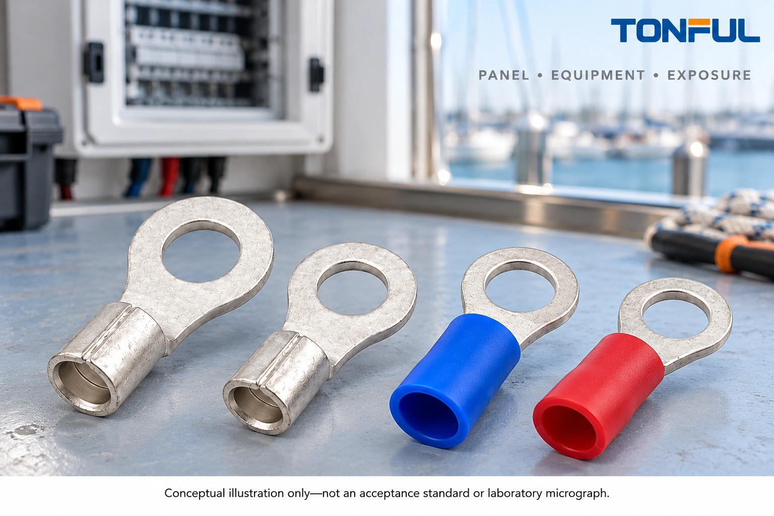
Marine terminal selection must account for the connection point and its location on the vessel. A terminal behind a protected distribution panel faces different conditions from a termination exposed to condensation, washdown or machinery movement. The word marine on packaging does not establish compatibility, sealing or installation approval.
Choose the terminal barrel for the conductor, its tongue or contact for the equipment interface, and its protection for the actual exposure. Then record how the complete connection will be assembled, inspected and accessed for service. No terminal finish can compensate for an incompatible stud connection or an uncontrolled moisture path.
This guide is a component-selection aid for qualified builders, engineers and marine electrical professionals. It is not a complete boat-wiring design or a live-work instruction. Applicable vessel rules, project requirements and equipment instructions govern the final installation, including circuit protection, conductor sizing, grounding and bonding.
Jump to: Map location, Match hardware, Specify protection, Control installation, Inspect and service, Prepare sourcing.
Map the Marine Terminal Selection Environment
Describe the actual exposure zone
Start with panel or equipment identity and physical location. Record whether the connection is protected from water, subject to condensation, exposed to spray or washdown, or located where leaks can accumulate. Include temperature, vibration, fluids and access limitations from the equipment design and vessel operating conditions.
Do not reduce all these conditions to a single waterproof requirement. Spray, standing water, repeated wetting and condensation inside an enclosure can enter through different paths. Select protection around the complete assembly and its installation, not just the terminal sleeve.
| Location condition | Selection question | Installation review |
|---|---|---|
| Protected panel interior | What end treatment does the hardware accept? | Covers, barriers and wire support |
| Condensation-prone enclosure | Where can moisture collect or travel? | Entries, drainage and inspection access |
| Splash or washdown exposure | What complete assembly protection is specified? | Seals, transitions and mounting |
| Machinery-mounted equipment | What movement reaches the termination? | Strain relief and routing |
| Restricted service space | Can the connection be inspected safely? | Access, identification and removal method |
Separate electrical isolation from switch position
A vessel may have batteries, shore power, an inverter, a generator and charging sources. An off switch is not proof that every nearby conductor is isolated. Follow the vessel and equipment procedures to isolate sources, verify the safe condition and address stored energy before work.
As a product-specific example, Blue Sea Systems distribution-panel instructions explicitly address disconnecting both AC and DC sources before installation. Use the current instructions for the actual equipment and qualified personnel; do not apply that document’s panel ratings or historical standards references to an unrelated installation.
Keep ignition-protection suitability separate from terminal selection. A covered terminal does not make a panel suitable for an explosive atmosphere. Equipment placement in fuel- or battery-related spaces requires the applicable design and equipment review, not an inference from terminal insulation.
Match Terminals to Panel and Equipment Hardware
Select the barrel and tongue independently
The barrel must accept the specified conductor material, strand construction and cross-sectional area. The tongue must fit the equipment’s mounting interface. Record both dimensions rather than choosing a terminal only because its hole passes over the stud.
For ring terminals, check hole size, tongue width, seating area, sleeve clearance and access for the specified hardware. An oversized ring or a tongue that sits on a barrier instead of the contact surface is not corrected by tightening harder. Do not modify the hole or tongue without an approved engineering process.
Fork terminals may be convenient for service, but use them only where the equipment and project requirements permit them. Do not generalize their suitability from a nearby connection. Quick disconnects likewise require the correct mating interface, retention and protection; a similar tab outline is not sufficient.
Review the TONFUL wire-terminal range as a starting point for these interface questions. An actual quotation should identify the terminal drawing and the equipment connection it is intended to serve.
Respect device-specific connection methods
Some equipment uses a clamp designed for prepared stranded wire or a compatible ferrule rather than a ring or fork. Follow its permitted conductor types, end treatments, strip length and insertion method. Do not force a tongue terminal into a clamp entry or assume every screw visible on a device is a screw-terminal landing point.
For nylon-insulated terminals, verify sleeve fit and surrounding clearances without assuming the insulation creates a water seal. For non-insulated terminals, define the approved insulating, guarding and environmental protection arrangement around the finished connection.
Do not add terminals to an existing stud stack without reviewing the equipment’s permitted arrangement and project requirements. Hardware engagement, contact surfaces, cover fit and service access all matter. Circuit identification should remain readable after the final assembly is closed.
Specify Materials and Complete Connection Protection
Ask for a finish specification, not a color
Identify base metal and plating from the part drawing and supplier documentation. Tinned appearance does not establish coating thickness, coverage or suitability for every mating material. Confirm the intended conductor and hardware combination rather than using the same finish description for every connection on the vessel.
Where dissimilar metals or an aggressive environment matter, obtain application-specific guidance from the design owner and component suppliers. Any protective compound must be approved for the materials and interface. Do not introduce an unspecified grease or coating that could change contact behavior, seal compatibility or installation torque assumptions.
Salt-spray claims need context. Ask which specimens, assembly state, exposure method and acceptance criteria produced the claim. Chamber hours alone do not establish field service life or waterproofing. No salt-spray duration or corrosion-performance figure is assigned to an unidentified terminal here.
Treat moisture paths as an assembly problem
Protection may involve a compatible sealed termination, approved heat-shrink system, enclosure entry, cover and routing arrangement. Confirm the intended overlap, wire insulation compatibility and installation method for each component. A protected barrel still leaves other interfaces that may need protection.
The marine heat-shrink guide addresses tubing selection around boat wiring. Use it alongside the actual termination and equipment instructions, not as a blanket approval to cover a defective crimp. Tubing cannot restore cut strands or make an oversized barrel acceptable.

Control Preparation, Crimping and Installation
Preserve the conductor and the intended interface
Inspect wire condition before selecting a repair termination. If moisture or corrosion has progressed beneath the insulation, follow the authorized assessment and replacement procedure rather than attaching a new terminal to visibly compromised conductor. Preserve removed parts if the cause needs investigation.
Strip to the specified length without cutting strands or damaging insulation. Confirm conductor insertion, barrel fit and support position before crimping. Do not remove strands to fit a smaller barrel, fold wire to fill a larger barrel or add solder as an improvised correction for uncertain tooling.
Use the identified crimping-tool system for the terminal, wire and insulation construction. A broad wire-range marking is not enough to approve the die profile. Record tool and cavity identity and perform the prescribed first-piece or repair verification.
If controlled pull or electrical tests are required, obtain sample quantity, fixtures, conditions and limits from the approved plan. A casual hand tug and continuity indication do not establish every mechanical or environmental requirement. Destructively tested samples are not installed back into service.
Install the hardware and protection as specified
Seat the terminal flat and use the equipment’s hardware arrangement and tightening instruction. Do not infer torque from stud size alone. Restore covers and barriers, and check that insulation is not pinched or forced against a sharp edge.
Support the cable so vessel movement and maintenance handling do not load the terminal barrel or equipment stud. Allow the routing and service space required by the design. Complete environmental protection only after the relevant workmanship checks, so a covering does not hide an unresolved defect.
For heat-applied protection, follow the component’s approved installation and vessel fire-safety precautions. Do not use open flame near fuel vapors, battery gases or combustible material. Qualified personnel should determine whether the location is safe for the prescribed equipment and process.
Inspect Connections and Plan Service Access
Inspect more than external cleanliness
Check terminal identity, conductor condition, insulation position, crimp location, flat seating, hardware condition and routing. Inspect the specified sealing or covering features without treating a smooth outer sleeve as proof of a sound electrical interface. Confirm that required protective covers and labels are restored.
| Inspection finding | Immediate response | Evidence to collect |
|---|---|---|
| Discoloration or residue | Isolate and assess before continued use | Location, photos and moisture history |
| Loose or moving terminal | Hold affected connection | Hardware, torque instruction and support condition |
| Damaged sleeve or seal | Review exposed interface | Part identity and installation record |
| Corrosion beneath insulation | Follow approved conductor assessment | Extent, routing and water-entry evidence |
| Repeated service damage | Review access and routing design | Repair history and removal method |
Do not tighten or clean a suspect connection before preserving evidence needed for a failure investigation. After an authorized repair, repeat the affected checks and document the final disposition. A replacement terminal alone does not prove the moisture source or mechanical load was corrected.
Set inspection frequency from risk and instructions
Use equipment instructions, vessel maintenance requirements and observed conditions to establish inspection intervals. Do not invent one universal calendar interval for every boat and location. Connections exposed to repeated wetting or machinery movement may need a different plan from a protected panel interior, subject to the governing maintenance program.

Prepare a Marine Terminal Sourcing Record
Request a part-specific recommendation
Send TONFUL the circuit application, wire construction, receiving hardware, exposure zone and required insulating or sealing method. Include equipment instructions, drawings, applicable project requirements and the evidence expected with samples. State clearly whether the connection is inside a protected panel or exposed at equipment.
Ask for terminal drawings, material and finish information, compatible tooling and confirmation of any unverified protection or test claims. Keep vessel compliance and complete-assembly ratings with the responsible design review; a generic terminal quotation cannot establish them.
Keep unresolved questions visible in the sample request. Assign an approval owner for an uncertain hardware arrangement, an exposure assumption or a proposed protective material. Do not release the sample for installation until those decisions are documented; purchasing availability does not resolve engineering compatibility.
The best sourcing record connects the offered part to the conductor, equipment interface, environmental protection and installation evidence. That makes marine terminal selection a reviewable engineering decision rather than a purchase based on color, packaging language or an unsupported promise of waterproof performance.